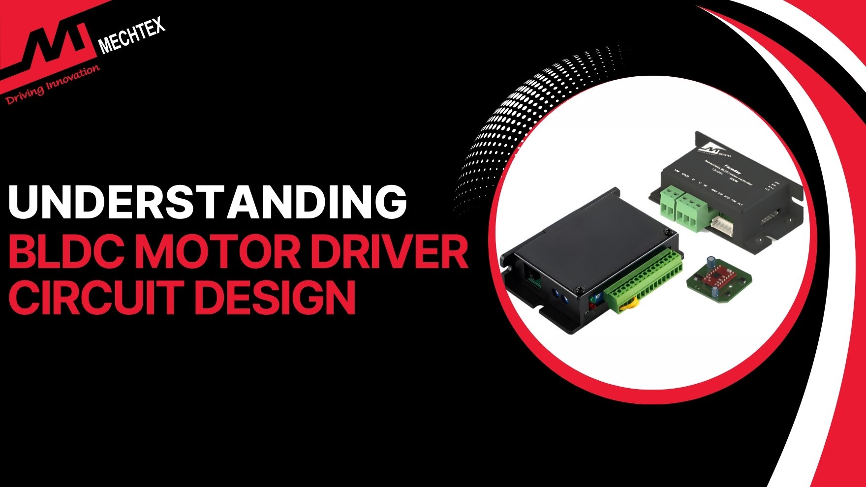
BLDC Motor Driver Circuit Design
A BLDC driver is an electronic control unit that regulates the flow of electric power delivered to stator windings. It consists of multiple components such as Power Supply Unit, Power Switching Devices, Gate Driver Circuit and Control Unit, that work together for reliable BLDC motor operation.
BLDC motors, also known as brushless DC motors, are widely used in industrial automation, electric vehicles, robotic and HVAC systems due to their high efficiency, long life, and better speed control.
Unlike Brushed DC motors, which operate with brushes and a commutator.
BLDC motors require an electric motor driver circuit to perform commutation for better speed and torque control. In this blog, we will explain the fundamentals of the BLDC motor driver circuit, its structure and key components, and practical design considerations.
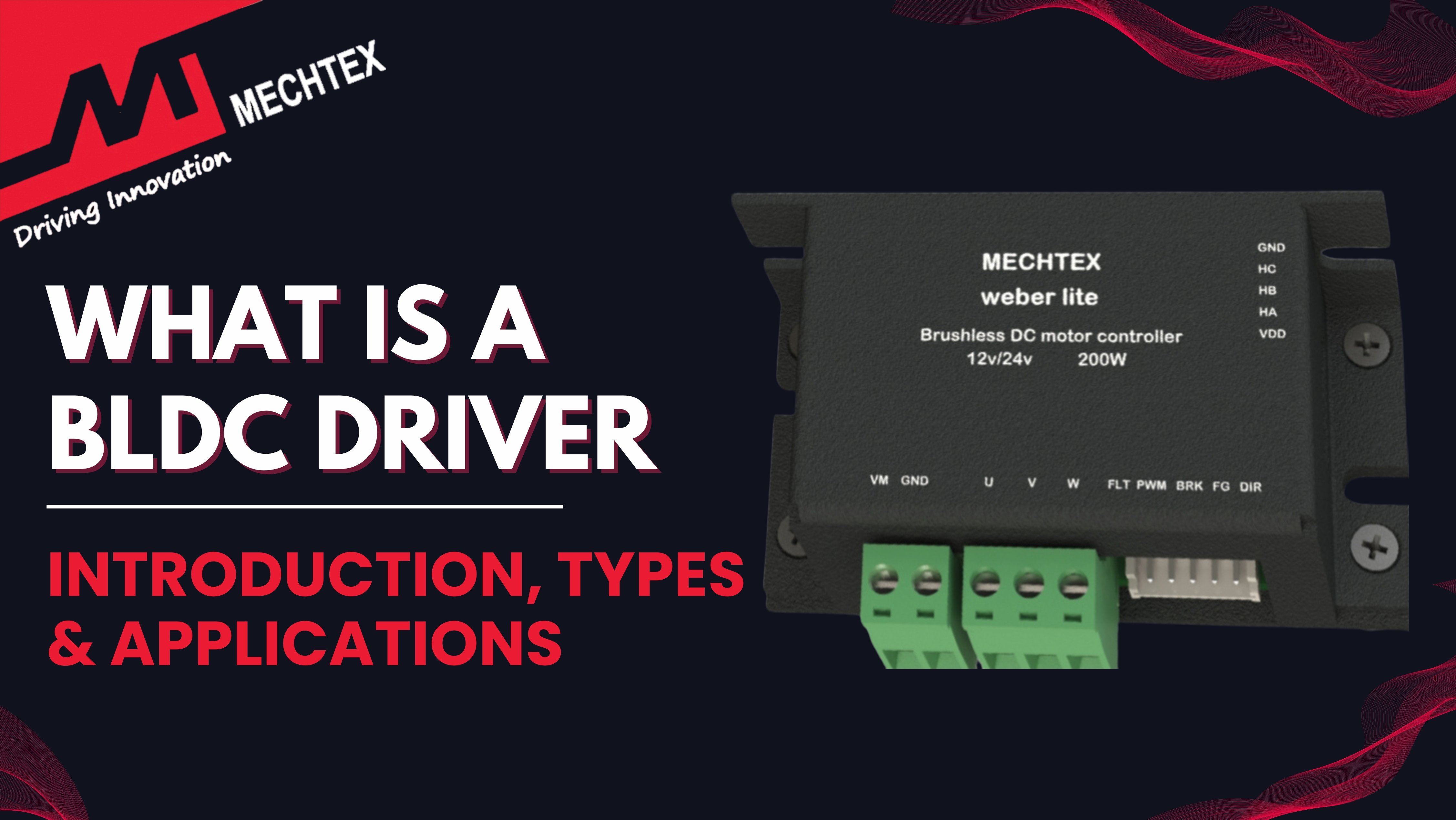
What is a BLDC Driver
A BLDC driver is an electronic control unit used to manage the operations of brushless DC motors (BLDC motors), by regulating how electric power is delivered to stator windings.
Since BLDC motors do not use brushes, the BLDC driver performs electronic commutation nd replaces the mechanical switching with precise semiconductor-based control.
A BLDC driver converts the DC power into a three-phase output using power devices such as MOSFETs or IGBTs. By switching between these power devices in a sequence, the BLDC driver generates a rotating magnetic field to produce torque.
In addition to the commutation, the BLDC driver also regulates speed, torque and direction of the BLDC motor. Also, many BLDC drivers incorporate protection features such as overcurrent, overvoltage, and thermal protection.
Overall, a BLDC driver is essential to ensure efficient and precise operation of BLDC motors across various applications.
Also Read
What is a BLDC Driver| Introduction, Types and Applications
Why a BLDC Motor Needs a Driver Circuit
As BLDC motors replace the mechanical commutation with electronic commutation for operations. Therefore, it uses a driver circuit to energise the stator windings in a specific sequence and generate rotation.
A BLDC driver circuits perform various functions in a BLDC motor for smooth and reliable operations. Some key functions performed by BLDC drivers are:
- Convert the DC supply into a three-phase output
- Determine rotor position using sensors
- Optimum switch between the power supplies in the correct sequence.
- Regulate speed, torque and direction
Without a driver circuit, a BLDC motor cannot start or operate reliably.
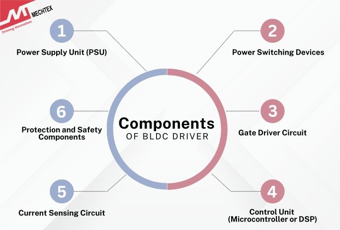
Components of BLDC Driver Circuit
A BLDC driver is built using multiple blocks or components that work together to achieve accurate commutation and reliable operation. Each block plays a significant role in handling power conversions and smooth operation.
The key Components of the BLDC driver include Power Supply Unit, Power Switching Devices, Gate Driver Circuit and Control Unit.
Let's deep dive into the details of the following block for better understanding:\
- Power Supply Unit (PSU)
The power supply unit provides the required DC voltage supply to both BLDC motors and the driver efficiently.
Generally, two voltage levels are used in power supply units: high voltage supply for the motor and a low voltage supply for the driver for control circuitry.
Proper voltage regulation and filtering are required for reliable operation and to prevent noise from other components.
- Power Switching Devices
Power switching devices are the core of the BLDC driver. MOSFETs or IGBTs are the most common power switching devices used to switch current through stator windings.
These devices are arranged in a three-phase inverter configuration to enable sequential energising of stator windings.
MOSFETs are preferred for low-voltage applications, while IGBTs are used in high-voltage applications for high efficiency.
- Gate Driver Circuit
Gate driver circuit is an interface between the power control units and the power switching devices. Its main role is to provide the correct gate voltage to turn on and off the MOSFETs and IGBTs efficiently.
High-side and low-side gate voltages are used to handle different power levels efficiently to ensure fast switching and reduced losses of the current.
- Control Unit (Microcontroller or DSP)
The control unit is the brain of the BLDC driver circuit. It generates commutation signals based on the rotor’s position and provides them to the BLDC driver for speed and torque control.
Microcontrollers and Digital Signal Processors (DSPs) are commonly used control units due to their ability to manage PWM generation, timings of energising, and real-time processing.
- Current Sensing Circuit
The current sensing circuit enables torque control and provides system protection. Shunt resistors or hall-based sensors measure DC supply. The controller uses this data to regulate current, improve efficiency and enhance system protection.
- Protection and Safety Components
Protection components prevent damage to the motor and circuit, and protect them against overcurrent, overvoltage and short circuits. Fuses, temperature sensors, and transient protection devices improve overall reliability.
Conclusion
BLDC motor driver circuit design is complex, but helpful to the engineers to combine power electronics, embedded control and system optimisation. A well-designed BLDC driver ensures precise commutation, efficient power conversion and reliable operation across a wide range of applications.