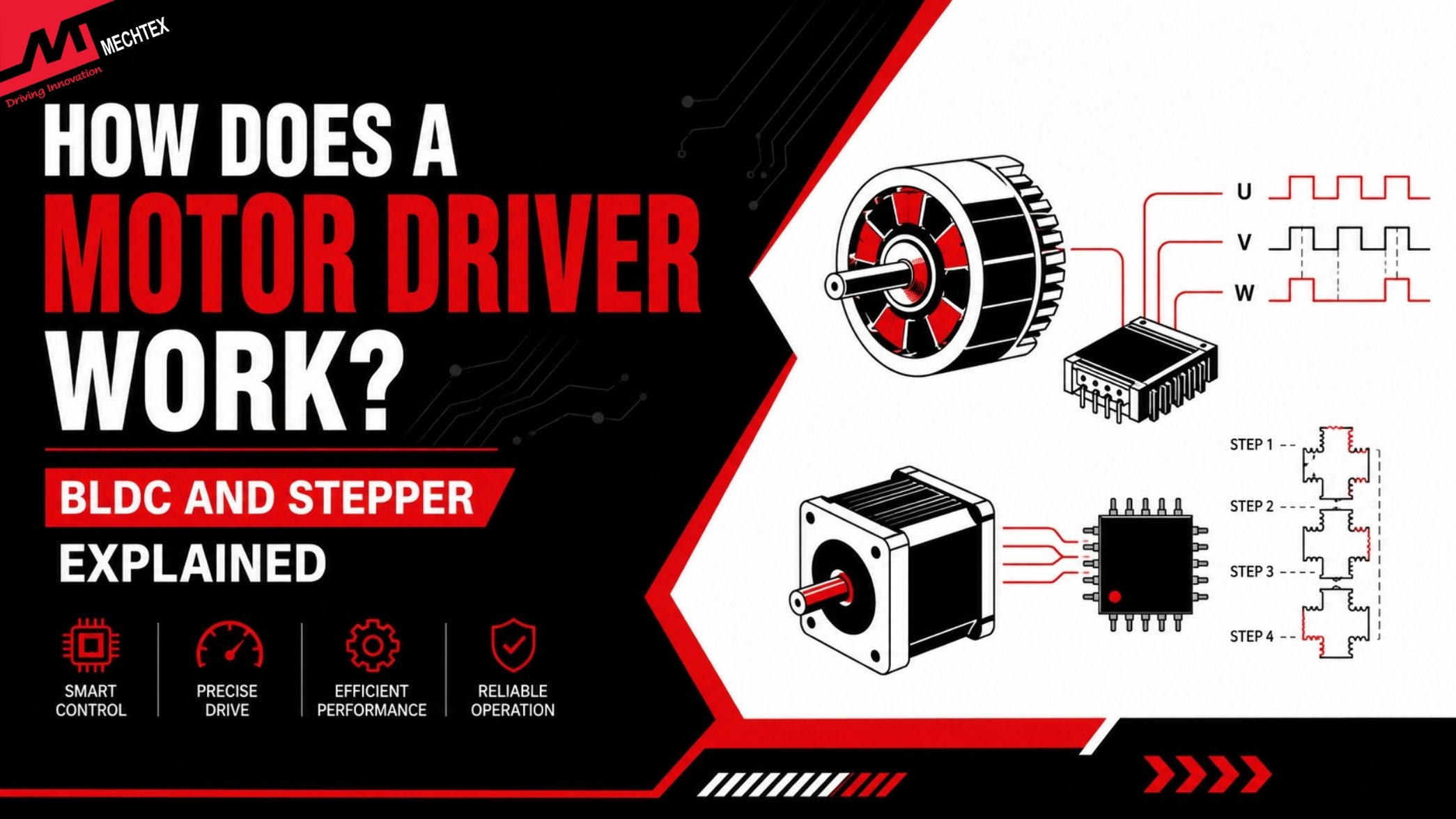
How a Motor Driver Works? Step by Step Working Principle of BLDC & Stepper Drivers
A motor driver works by regulating the power supply into an electric motor by switching the sequence. It also controls its speed, direction, and position for efficient operation. This blog covers the working principle of BLDC drivers and stepper drivers with a their comparison. table.
Motor Drivers are electronic devices which regulate the power supplied to electric motors and control its speed, direction, and torque. It works as an interface/bridge between the controller and the electric motor. It also converts the signals received from the controller into electrical outputs for smooth operation.
By controlling current flow and its switching sequences, the motor drivers ensure reliable performance of various applications.
Among the various motors and control systems, BLDC (Brushless DC) motors and stepper motors require drivers to work efficiently. In this blog, we will learn about the step-by-step workings of a BLDC driver and a stepper driver, and we will study a comparison table to understand the key differences between them.
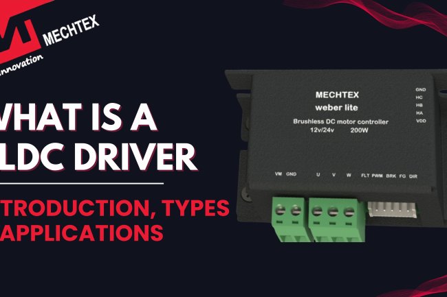
Also Read: What is a BLDC Driver | Introduction, Types and Applications
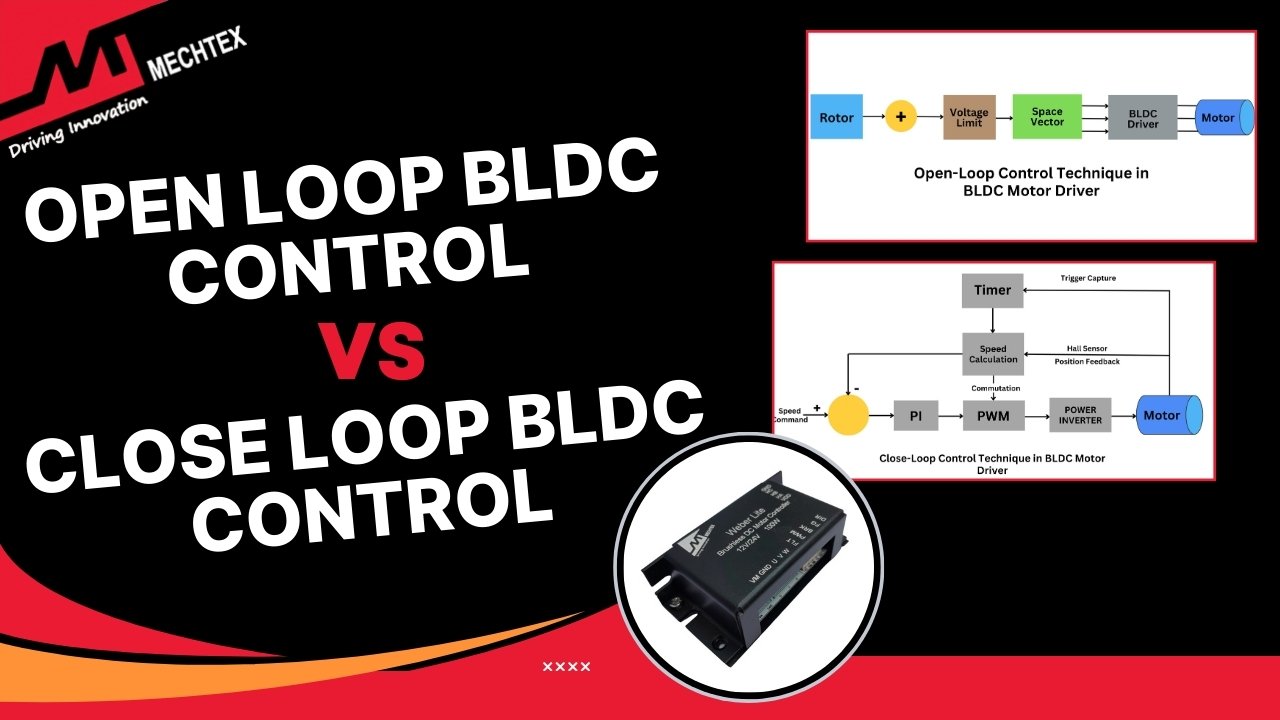
How does a BLDC Motor Driver Work?
A BLDC (Brushless DC) driver regulates the operation of the Brushless DC motor by switching the MOSFETs in a particular sequence and creating a rotating magnetic field. The Microcontrollers (MCUs) detect the speed and position of the motor and send the information to the gate driver. The gate driver converts the signals into the power to switch the MOSFETs and enable smooth and precise operation.
Let's deep dive into the step-by-step working of a BLDC driver:
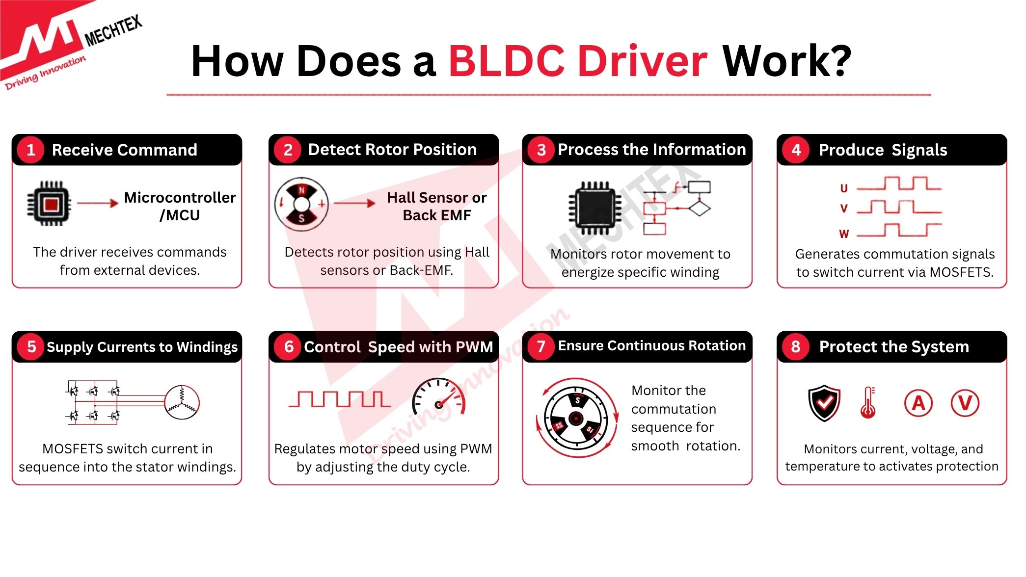
Step 1: Receive Command
The motor driver receives the command from the external devices, such as Microcontrollers and flight controllers. These commands provide information about the speed, torque, and direction of the motor.
Step 2: Detect the Rotor Position
To supply the power to the correct motor winding, a BLDC driver must have information about the rotor’s position. This information is received either from Hall sensors (in a sensored BLDC motor) or from Back-EMF (in a sensorless BLDC motor).
Step 3: Process the Information
The driver continuously monitors the rotor movement and decides which winding of the motor should energise to create a rotating magnetic field.
Step 4: Produce Commutation Signals
Depend upon the rotor position, the BLDC driver produce signals for switching current. These signals are managed by the power transmitters such as MOSFETs which are arranged in three-phase bridge circuit.
Step 5: Switch Current into the Motor Winding
The MOSFETs switch the current in a specific sequence into the stator windigs. This creates a magnetic field which interacts with rotor and create movements.
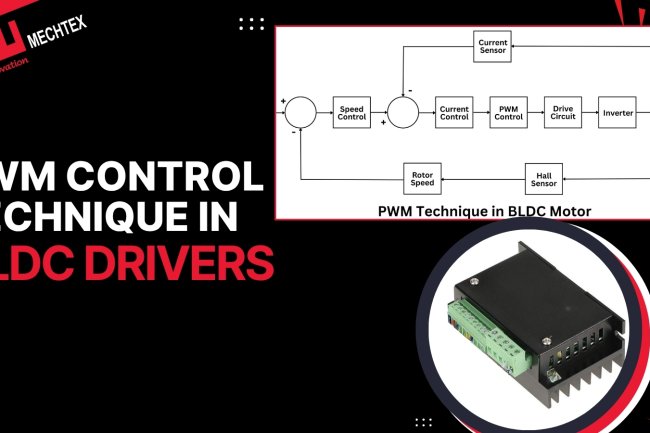
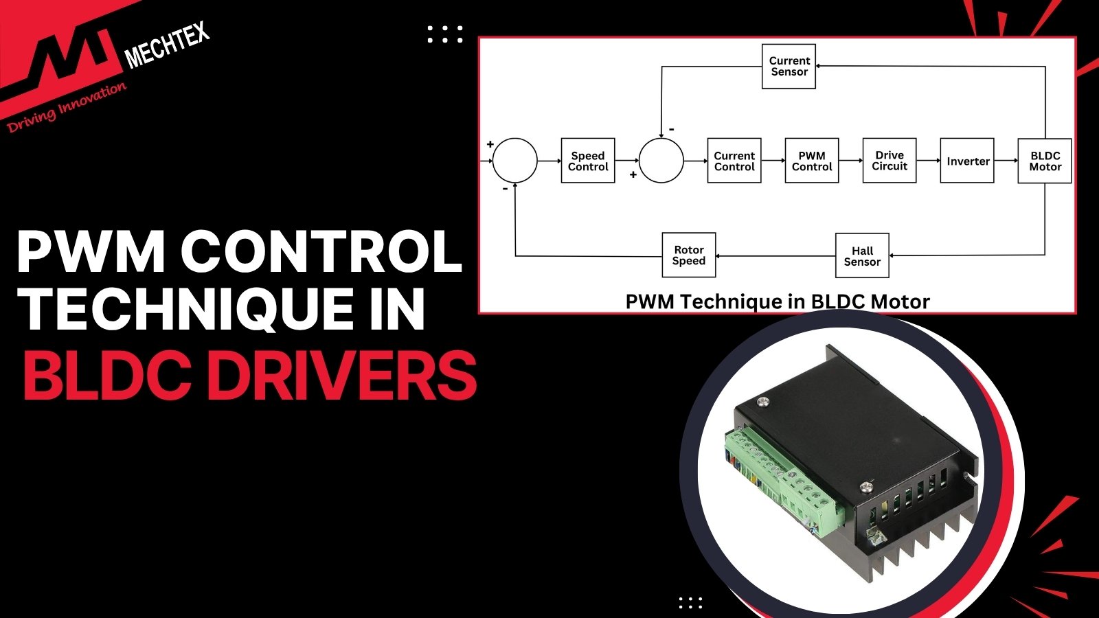
Step 6: Regulate Speed using PWM
The BLDC driver regulate the speed of BLDC motor by using Pulse Width Modulation (PWM) Technique. By changing the duty cycle, it also control the voltage and current supplied to the motor.
Step 7: Ensure Continuous Rotation
When rotor moves, its position changes with every movement. The driver monitors the commutation sequence and ensures the rotor is synchronised with the stator’s magnetic magnetic for smooth rotation.
Step 8: Protect the Motion System
The BLDC driver continuously measure the parameters such as current voltage, and temperature of the system. If any parameters exceed the limit, the driver enable the protection mechanism to avoid failures.
How does a Stepper Motor Driver Work?
Unlike the BLDC (Brushless DC) driver, which depends upon the continuous rotor movement to determine the switching sequence. The stepper driver works blindly, meaning it supplies current to each winding without any sequence and assumes that the rotor will move parallel to each energised winding. Here is a complete step-by-step working of the stepper driver:
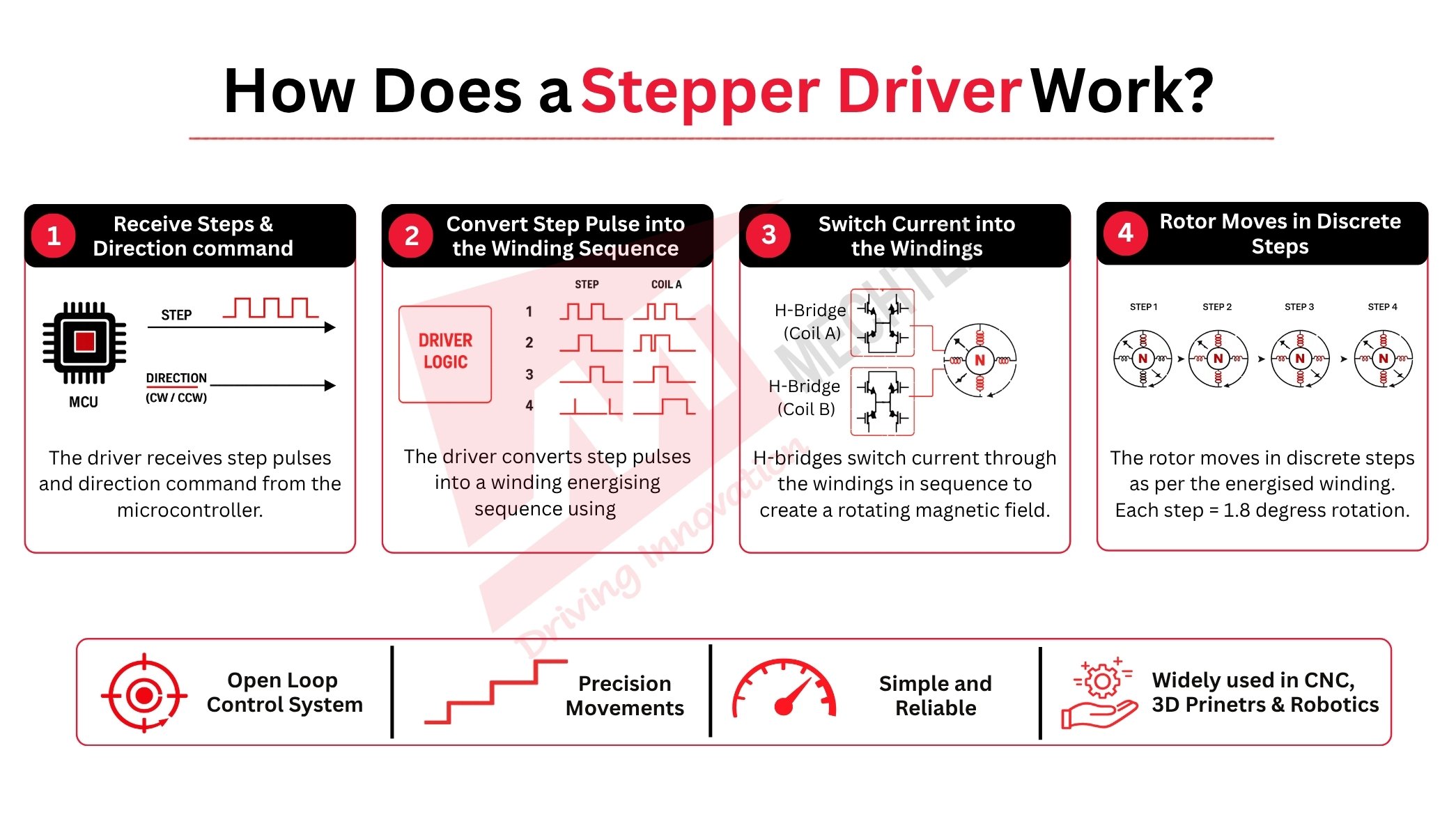
Step 1: Receive Steps and Direction Command
The stepper driver receives two different commands from the Microcontroller (MCUs): a) Step Command, b) Direction Command.
Each step command allows the stepper motor to move by one increment (in discrete steps). The direction command allows the motor to move in a particular direction. If the direction command is HIGH, it means the stepper motor will move in a clockwise direction, and if it is LOW, it means the stepper motor will rotate in an anti-clockwise direction.
Unlike the BLDC driver, which works as per the PWM signals, the stepper driver allows movement based on each discrete step.
Step 2: Convert Step Count into the Winding Sequence
The stepper driver's internal logic algorithm reads the STEP command from the microcontroller (MCU) and converts it into a command to energise the motor windings. It does not detect the rotor position to determine the energising sequence. It energises the winding of the stepper motor irrespective of the rotor position. This makes the stepper driver an open-loop control system.
Step 3: Switch Current into the Windings
The stepper driver uses two H-bridges (one for each coil) to switch the current into the windings in the proper sequence. The energised creates a rotating magnetic field and attracts the rotor to lock the synchronisation. A current chopper circuit continuously monitors the energised winding and switches the H-bridges quickly to maintain current flow in sequence.
Step 4: Rotor moves in discrete steps
The stepper motor moves in discrete steps as per the energised winding. It marks a complete one step. One step = 1.8 degrees or 200-step motor (as per industrial standard). When the microcontroller sends the next step command, the stepper driver energises the next winding of the motor, and the rotor moves accordingly.
The step command controls the speed of the stepper motor. "Fast command" means “high speed.”
BLDC Driver vs Stepper Driver: Comparison Table
Both BLDC drivers and stepper drivers manage the power supply to the windings of the motor, but with different operating principles. The BLDC driver uses an electronic commutation method to energise the windings, while the stepper driver uses a predetermined sequence to energise the windings.
Understanding the differences between the two drivers helps individuals to select the driver and motor combination for their application.
| Parameter | BLDC Motor Driver | Stepper Motor Driver |
|---|---|---|
| Working Principle | Electronically commutates motor phases based on rotor position | Energizes motor phases in a fixed sequence based on step pulses |
| Control Signals | Speed, torque, and direction commands | Step and direction pulses |
| Motion Type | Smooth continuous rotation | Precise step-by-step movement |
| Position Control | Requires feedback for high-accuracy positioning | Provides inherent positioning through fixed step angles |
| Speed & Efficiency | Higher speed capability and efficiency | Better suited for low-speed, high-precision applications |
| Typical Applications | Drones, HVAC systems, pumps, fans, and robotics | CNC machines, 3D printers, medical devices, and automation equipment |
This table explains that the BLDC drivers are suitable for high-speed applications and that stepper drivers are used in applications that require high accuracy.
How Motor Driver Protection Works during the Operation
The Motor drivers continuously track the critical electrical and thermal parameters of the motor, such as current, voltage, and temperatures, to prevent damage to the motor and driver. Let's see some important protection features of the driver:
- Overcurrent Protection
If an electric motor produces excessive current due to overload, the driver either limits or completely shuts off the supply to avoid damages.
- Overvoltage Protection
When the supply of the voltage exceeds its safe limit, the driver disconnects the input from the motor to protect the internal components of the motor.
- Undervoltage Protection
If the supply of the voltage is below its required limit, the driver stops functioning to avoid unstable operation.
- Thermal Protection
The temperature sensors continuously monitor the temperature of the driver circuit. If the sensor detects a rise in temperature, the driver reduces the power supplied to avoid a short circuit.
- Short Circuit Protection
If an abnormal spike in current occurs. It is immediately detected by the driver and disables the power to prevent damages.
By continuously tracking all the electrical and thermal parameters and responding to any changes in milliseconds, ensure the safe, reliable, and efficient operation of the motor.
Frequently Asked Questions
Q1. What is the difference between an H-bridge and a three-phase bridge?
An H-bridge consists of 4 transistors and controls the direction of current through a single DC supply. A three-phase bridge has 6 MOSFETs and produces the rotating magnetic field required for a BLDC motor.
Q2. What is current chopping in a stepper motor driver?
Current chopping is a technique mainly used by stepper motor drivers to manage the power supply to the windings of the motor. The driver rapidly switches the power between ON and OFF to maintain the desired current flow and avoid overheating.
Q3. How does a stepper motor driver know the rotor position?
A stepper motor driver does not directly detect the rotor position. It assumes that the rotor is moving as per the command pulses and counts the step pulses to track the position of the rotor for better accuracy.
Q4. Can a motor driver work without a microcontroller?
Yes, a motor driver can work without a microcontroller (MCU) if it receives commands or signals from other external devices such as a PLC or flight controller. However, most motor drivers use microcontrollers (MCUs) to provide better accuracy and control.
Q5. What is the role of the gate driver inside a motor driver?
A gate driver manages the switching of MOSFETs and IGBTs inside a motor driver. It regulates the low-voltage control signal and provides precise drive current, which enables the MOSFETs and IGBTs to turn the power supply ON and OFF rapidly and reliably.
Conclusion
Whether using a BLDC driver with three-phase commutation or a stepper driver with a predetermined sequence to detect the rotor position. Every driver converts the low-voltage signal into a sequential current flow for highly precise output.
Understanding their working principles and differences helps individuals to select the right motor and driver solutions for their applications.
Also Read: What is a BLDC Driver | Introduction, Types and Applications
Also Read: BLDC Motor Driver Circuit Design