Implementing PID Controllers for BLDC Motor Control
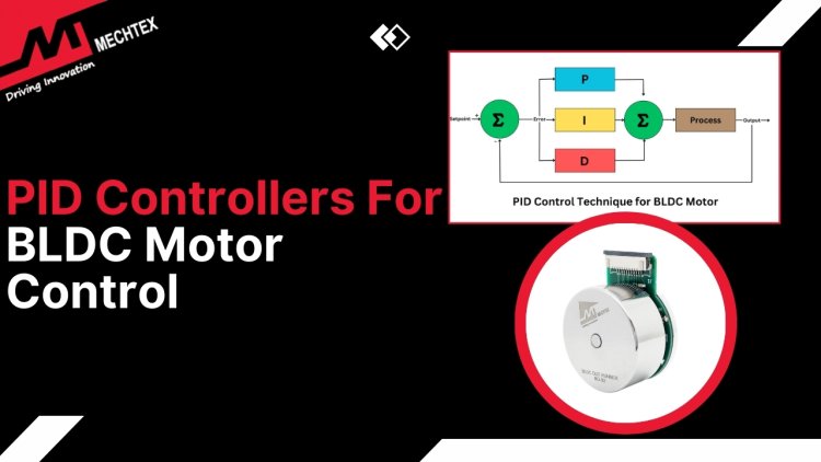
A PID controller is a feedback control mechanism that maintains the desired performance by minimising errors between the desired and actual BLDC motor state. It ensures precise speed and torque regulation and makes BLDC ideal for diverse applications.
BLDC motors are widely used in various applications due to their high efficiency, compact size, and low maintenance. However, precise control of BLDC motors, particularly in applications requiring variable speed and torque is critical. Proportional-integral-derivative (PID) controllers provide a reliable and straightforward method for achieving precision.
In this blog, we explore the basics of PID controllers for BLDC motor control, their advantages, and practical steps for implementation.
What is BLDC Motor?
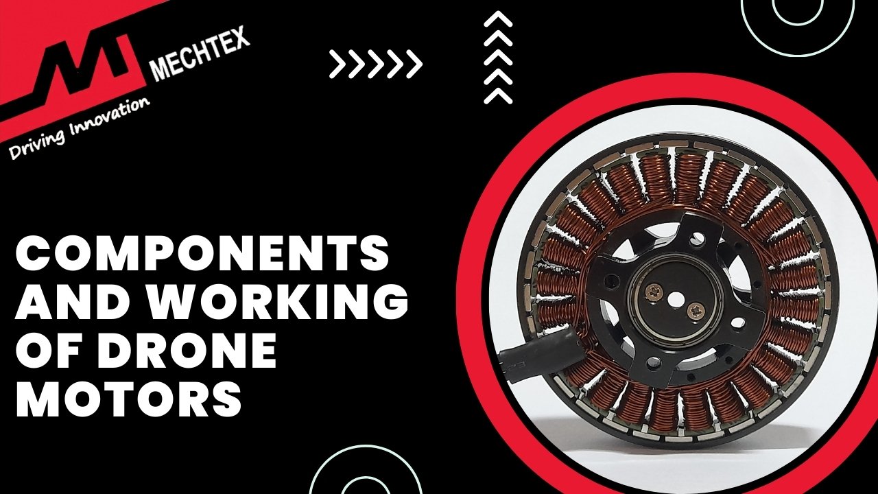
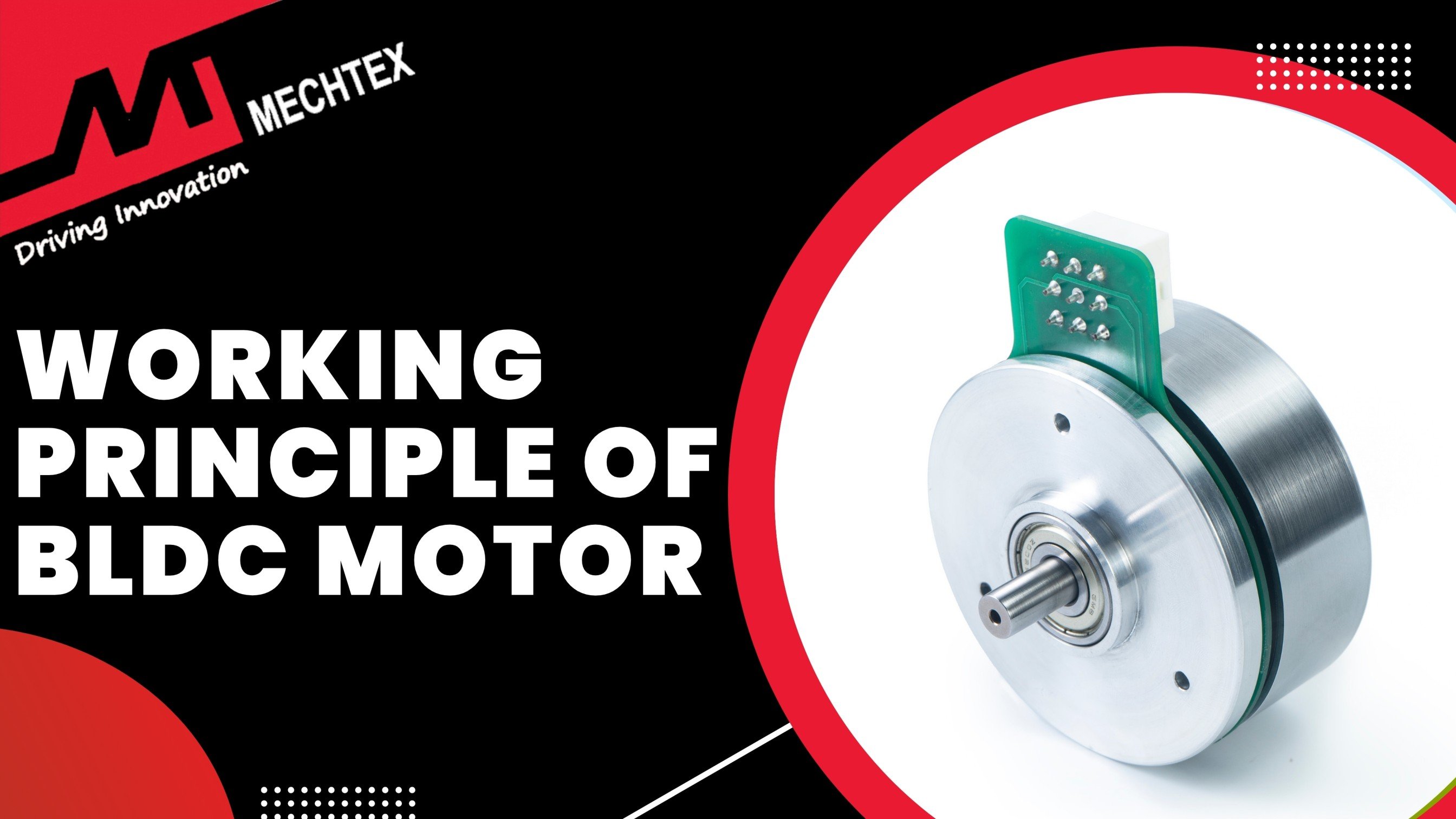
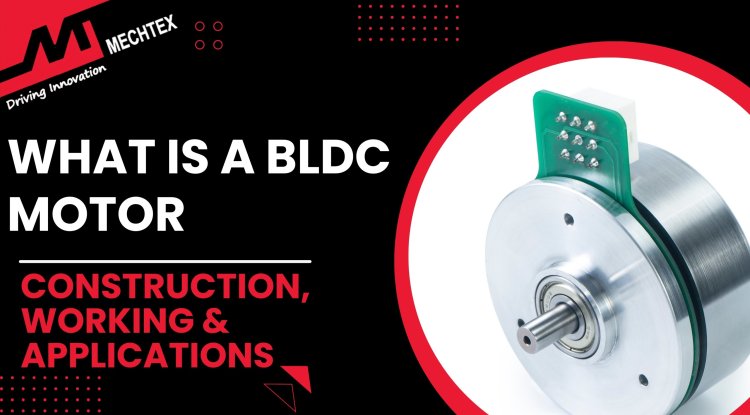
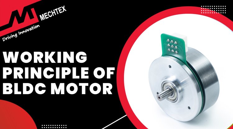
BLDC motor is an electric motor that eliminates the mechanical commutator used in traditional DC motors and replaces it with electronic commutation for high efficiency and reliability. The construction of the BLDC motor consists of a rotor which contains a permanent magnet and a stator includes a laminated iron core with winding.
The working of the BLDC motor is based on electromagnetic induction. A controller applies current to the stator winding in a sequence and creates a rotating magnetic field. It interacts with the rotor and causes it to turn. The absence of brushes reduces friction and wear leading to longer operational life and lower maintenance compared to brushed motors.
Key advantages of BLDC motors include high efficiency, precise speed control, and compact size. They are widely used in applications such as drones, electric vehicles, household appliances, and industrial automation.
Also Read
What is a BLDC Motor| Construction, Working and Applications
What is a PID Controller?
A PID controller (Proportional-Integral-Derivative controller) is a feedback control mechanism widely used in BLDC motor control to maintain its desired performance by minimising the error between the desired and actual BLDC motor state. Precise control of the BLDC motor is achieved through three components:
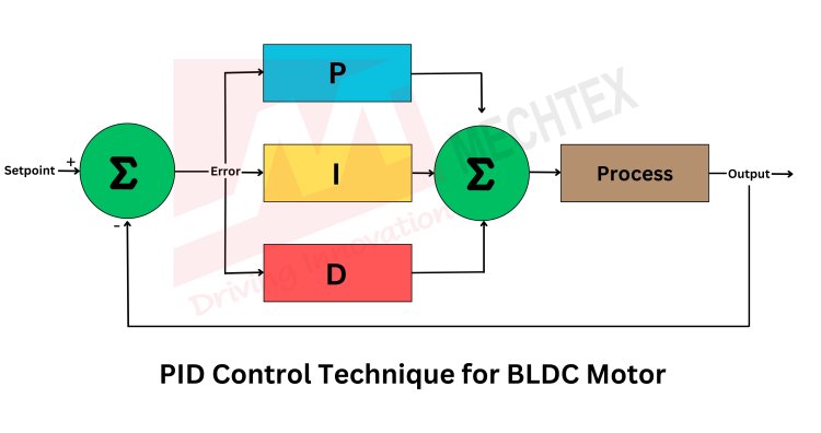
- Proportional Control (P)
This term is proportional to the error [e(t)] between the desired and actual BLDC motor speed or position.
P = Kp ∗ e(t)
where Kp is proportional gain.
It provides corrective force directly proportional to the error, responding quickly to deviations.
- Integral Control (I)
This term addresses the accumulated error over time to eliminate steady-state error.
I = Ki ∫ e(t)dt
where Ki is integral gain.
It ensures the BLDC motor reaches the exact setpoint even if the proportional term alone cannot do so.
- Derivative Control (D)
This term predicts future errors by considering the rate of change in error.
D = Kd​∗de(t)⁄dt
where Kd is the derivative gain.
It helps stabilise the system by damping oscillations and reducing overshooting.
The PID controller continuously calculates the control signal as the sum of the above three terms [u(t) = P + I + D] and it to the BLDC motor driver. This signal adjusts the BLDC motor's voltage or current to align its speed or position with the desired setpoint.
BLDC motors have non-linear dynamics due to their back-EMF and variable load conditions. A PID controller helps achieve precise control, compensating for these factors by dynamically adjusting the BLDC motor input to maintain stable performance.
Check out the video below by "Curio Res" for a visual explanation of the BLDC motor PID control.
Steps For Implementing a PID Controller
Implementing a PID controller for BLDC motor control involves a structured approach to achieve precise control over motor speed or position. Here’s a step-by-step guide:
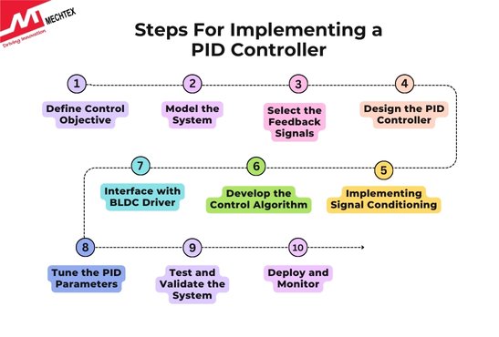
- Define Control Objective
Decide whether the PID controller is for speed control, position control or another parameter like torque. For instance, in speed control, the desired speed is maintained despite load variations.
- Model the System
Analyse the BLDC motor dynamics such as transfer function or state space representation. Identify key parameters like resistance, inductance, back-EMF constant, and inertia. Perform simulations to validate the BLDC motor's behaviour.
- Select the Feedback Signals
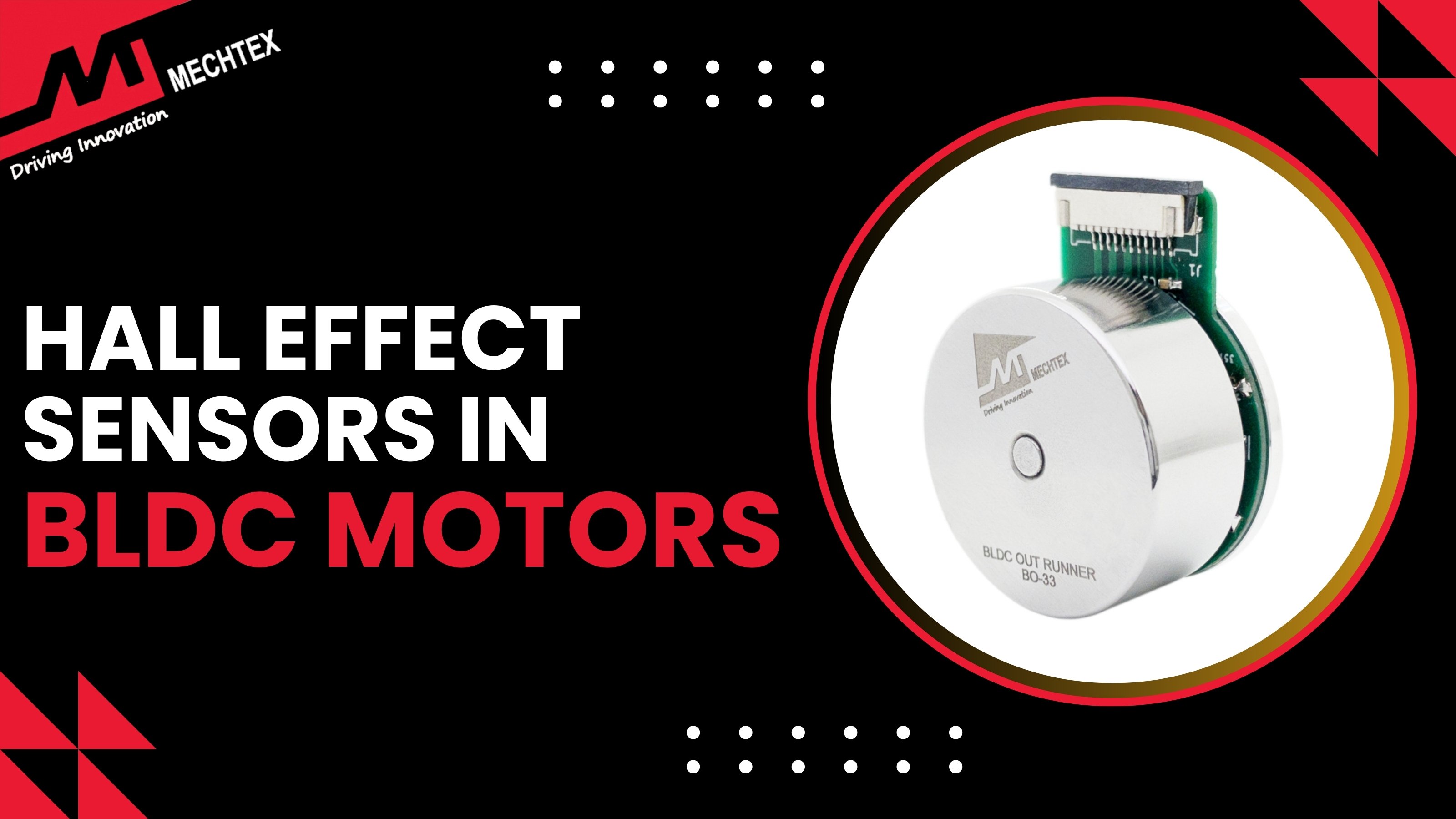
For speed control, use hall sensors, encoders, or tachometers for feedback. For position control, use encoders for precise positional data.
- Design the PID Controller
Proportional (P): Reacts to the error to reduce deviation.
Integral (I): Eliminates steady state over time.
Derivative (D): Predicts the error trend and dampens overshoot.
Set initial gains based on system dynamics and refine during tuning.
- Implementing Signal Conditioning
Process the feedback signals to minimise nose using filters such as low-pass filters. Scale the signals appropriately for PID controller input.
- Develop the Control Algorithm
Calculate Error: Error (t) = Setpoint - Measured Value
Apply the PID Equation: u(t) = Kp*e(t) + Ki ∫ e(t)dt + Kd​ de(t) / dt. Here, u(t) is the controller output.
- Interface with BLDC Driver
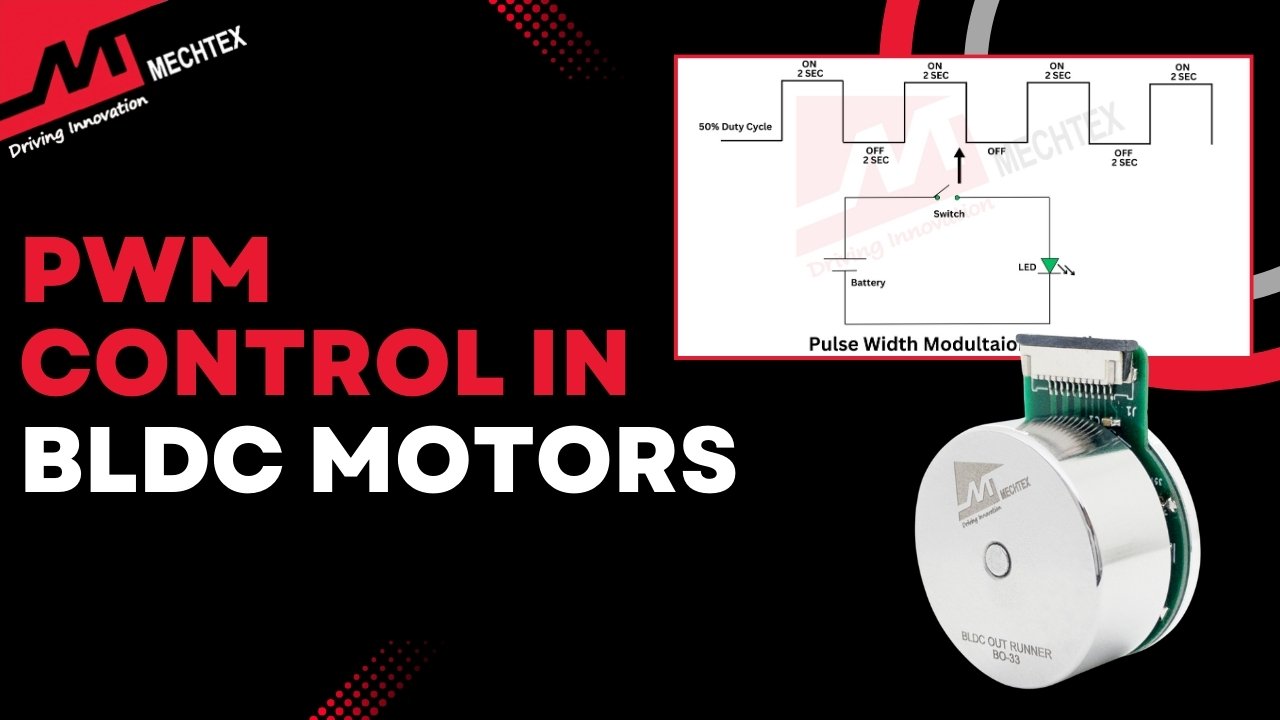
Convert the controller output to drive signals using PWM modulation. Ensure compatibility with the BLDC motor driver.
- Tune the PID Parameters
Use methods like Ziegler-Nichols, trial-and-error, or software tools to optimise Kp, Ki, and Kd. Focus on minimising overshoot, steady-state error, and achieving stability.
Test and Validate the System
Test under various conditions such as different loads, and changing setpoints. Verify if the system responds as desired with minimal lag and overshoot.
- Deploy and Monitor
Deploy the tuned PID controller to the application. Continuously monitor performance and adjust parameters if system dynamics change over time.
Advantages of Implementing PID Controllers for BLDC Motor Control
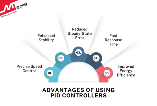
- Precise Speed Control
PID controllers ensure accurate speed regulation by continuously monitoring and adjusting the BLDC motor’s performance based on setpoints, minimising overshoot and undershooting.
- Enhanced Stability
The proportional, integral, and derivative terms effectively counteract disturbances and maintain steady-state operation to ensure the BLDC motor runs smoothly under varying loads.
- Reduced Steady-State Error
By addressing steady-state error through the integral term, PID controllers improve the BLDC motor’s accuracy in achieving the desired performance.
- Fast Response Time
The derivative term helps in anticipating and counteracting rapid changes in BLDC motor conditions to allow for quick adjustments to dynamic environments.
- Improved Energy Efficiency
By maintaining optimal BLDC motor operation, PID controllers minimise unnecessary power consumption leading to better energy management.
Conclusion
Implementing a PID controller for BLDC motor control ensures precise speed and torque regulation, making it ideal for diverse applications. By understanding the principles and practical steps outlined in this blog, one can successfully integrate PID controllers into BLDC motor systems, achieving reliable and efficient operation.
