How Does an Encoder Work? Step-by-Step Signal Flow for Optical and Magnetic Encoders
A complete step-by-step guide on how optical encoders and magnetic encoders work and generate signals. It includes quadrature output, pulse counting, and direction sensing.
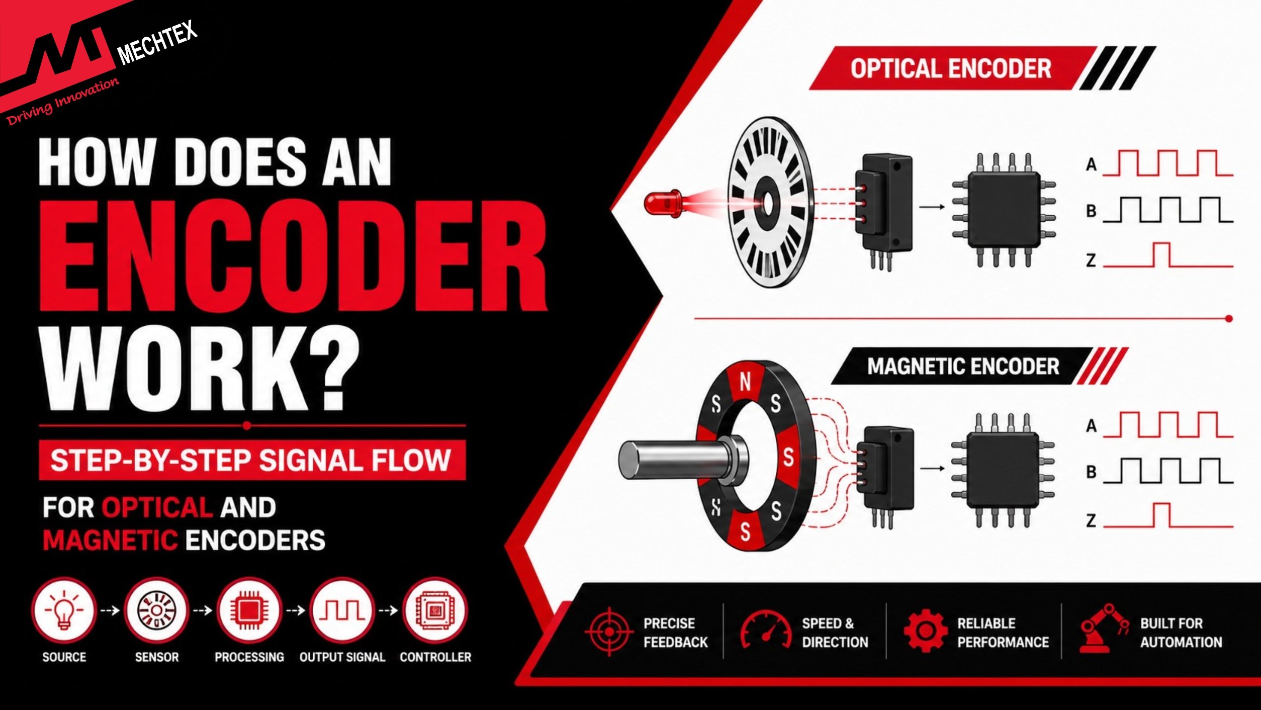
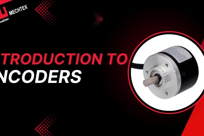
An encoder is an electromechanical device which converts the movements into electrical signals. It helps applications or systems to measure the speed, direction, and position of the motor for efficient operation.
It also works as a feedback device in motion control systems by continuously interpreting the motor's data to the controller or driver.
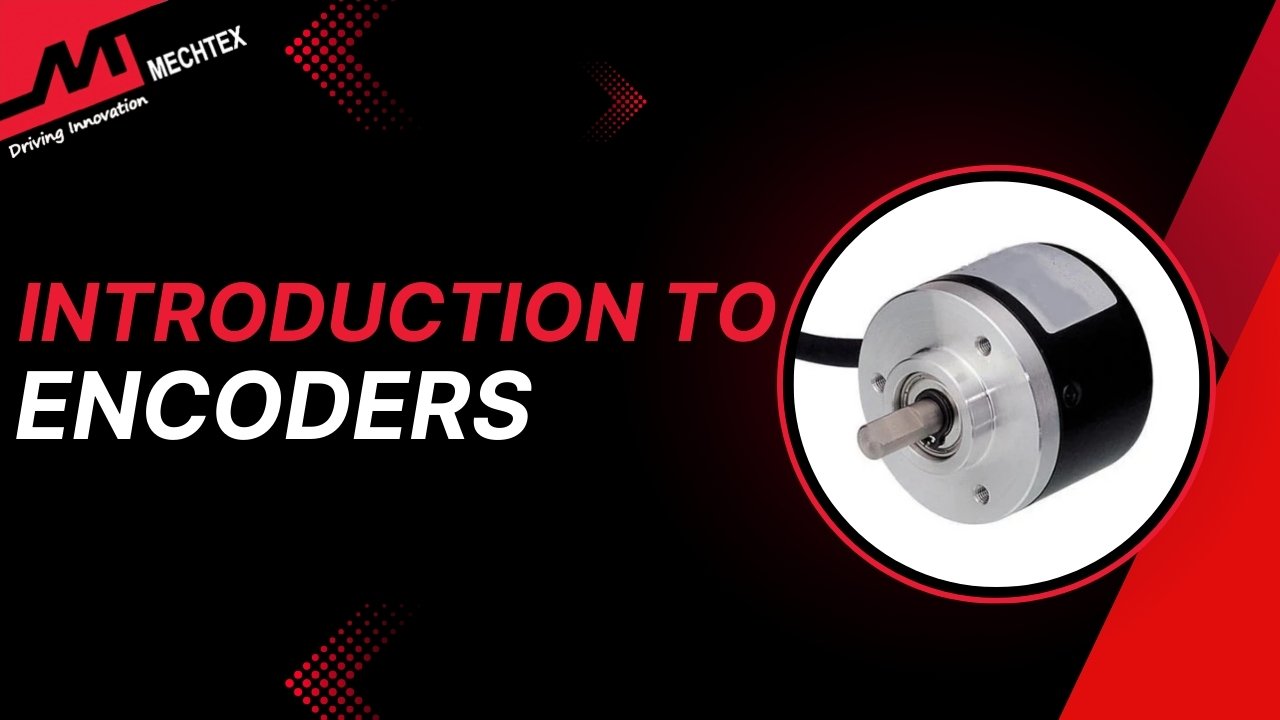
“If you want a broad guide about encoders (Introduction, Types & Applications), then read our blog: Introduction to Encoders”
In this blog, you will learn the step-by-step working principle of an encoder, including the working of optical encoders and magnetic encoders, how the quadrature A/B/Z signal generate, and how pulse counting helps motion control systems to monitor the movements of an electric motor.
Working of an Encoder
An encoder is a device which works by detecting the mechanical movement of an electric motor and converts it into electric signals. It converts movement into electrical signals with the help of a controller, PLC, or motion control system.
When the encoder shaft moves, a sensing device inside the encoder produces a series of pulses parallel to the movement of the encoder. This series of pulses helps to detect the speed, direction, and position of the motor. The controller converts the pulses into data to regulate the rotation of the motor.
Depending on the encoder type, their working mechanisms differ significantly. Let's get a deep dive into the working mechanisms of the optical encoder and magnetic encoder to better understand encoders.
How Does an Optical Encoder Work?
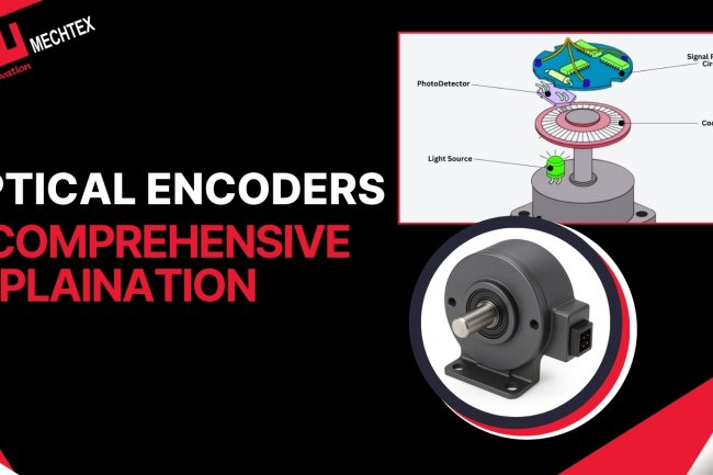
An optical encoder works by using a light interruption and a photo-sensing device. These devices detect the movement of the motor and convert it to electrical signals to provide speed, position, and direction feedback to the controller.
Components of Optical Encoder
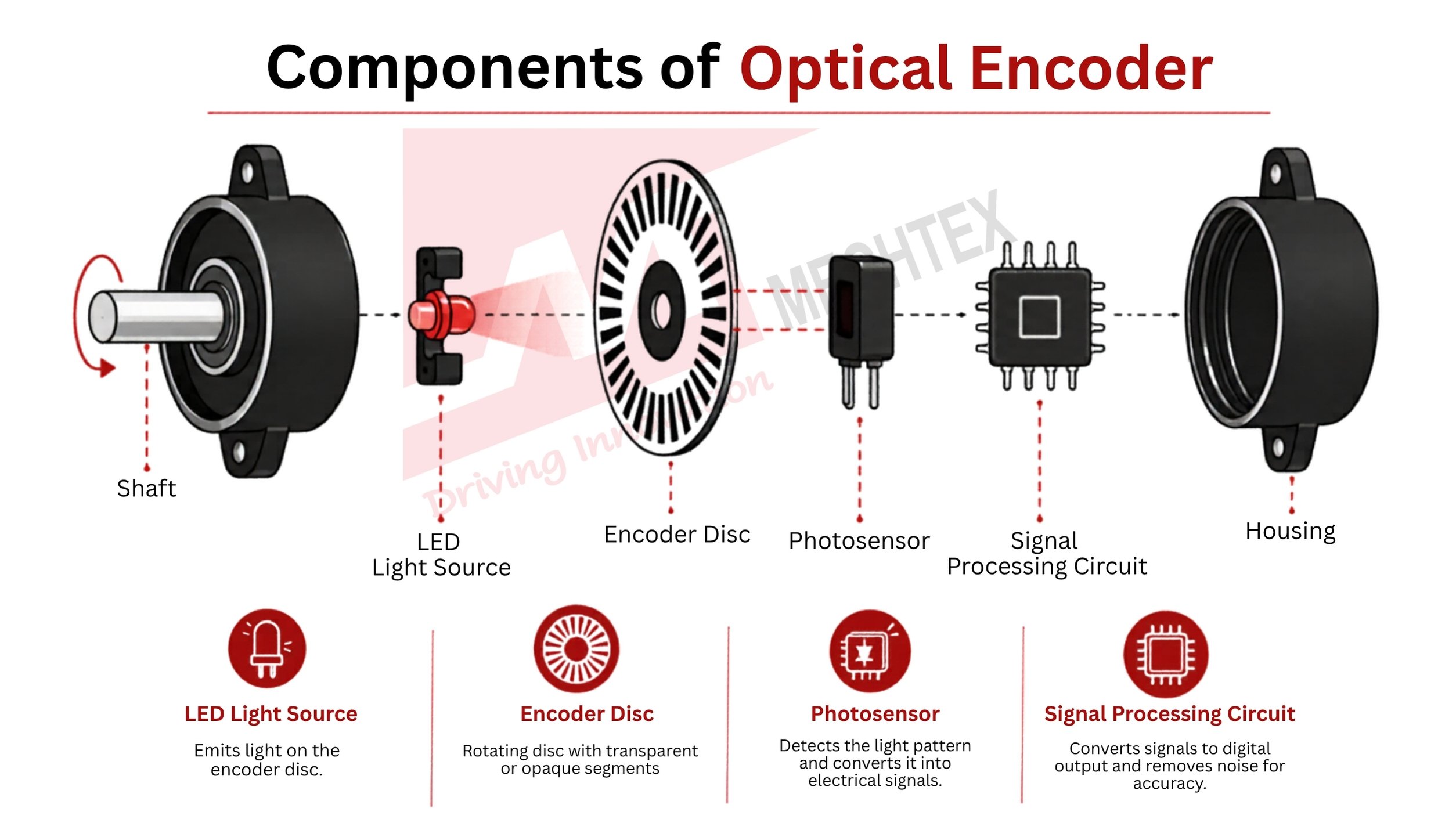
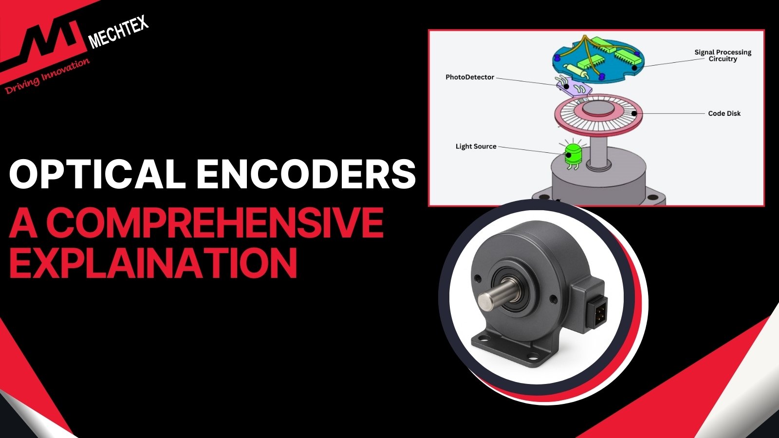
Optical Encoder includes several components such as LED Light source, Encoder Disc, Photosensor, Signal processing circuit, Shaft and Housing to detect the motion of a motor and convert it to signals for smooth operation. Each component performs different functions. Let's understand each component in detail:
- LED Light Source
It emits continuous light on the encoder disc. The stability of this light decides the accuracy of the electric signal. More stable light provides highly accurate data, while less stable light provides less accurate data.
- Encoder Disc
It is a rotating disc which contains transparent or opaque segments. This segment interrupts the light to detect the movement of the motor. The slot pattern on this disc dictates the encoder’s signal format.
- Photodetector/Photosensor
It identifies the pattern of the light and converts it into electrical signals. It also continuously monitors the changes in the light pattern to provide accurate data.
- Signal Processing Circuit
It converts the electrical signals into digital output and sends it to the controller. It also eliminates the electrical noise and other environmental parameters from the signal to improve its accuracy.
Step-by-Step Signal Generation
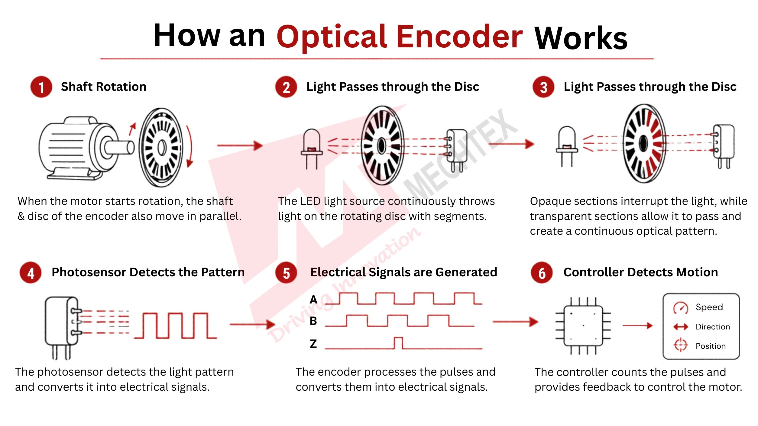
- Shaft Rotation
When an electric motor starts rotation, the shaft and disc of the encoder also move in parallel. This movement starts the process of creating the electrical signals.
- Light Passes through the Disc
The LED light source continuously throws the light on the rotating disc. This disc contains transparent or opaque segments, which interrupt the light. This rotating disc also decides how much amount of light must reach the photosensor at a particular moment.
- Light gets Interrupted
As the disc moves, the opaque section interrupts the light while the transparent section allows the light to pass through it. This is a continuous process that creates an optical pattern based on the movements.
- Photosensor Detects the Pattern
The photosensor detects the different light patterns and converts them into electrical signals. The frequency of these electrical signals depends on the motor’s rotational speed. As the rotational speed changes, the frequency of the pulse also changes accordingly.
- Electrical Signals are Generated
The optical encoder electronically processes the pulses and converts them into electrical signals. These electrical signals are determined as A, B and Z channels.
- Controller Detects Motion
The controller counts the pulses and provides feedback about the speed, direction, and movement of the motor. This feedback helps the motion control system to control the rotation of the motor.
Incremental Encoder vs Absolute Encoder Disc Pattern
In an incremental encoder, the rotating disc has transparent and opaque slots. These slots help the incremental encoder to generate pulses during the rotation. In an absolute encoder, the rotating disc contains various digital code tracks. Every movement of the shaft generates a unique digital code to determine the movement of the motor.
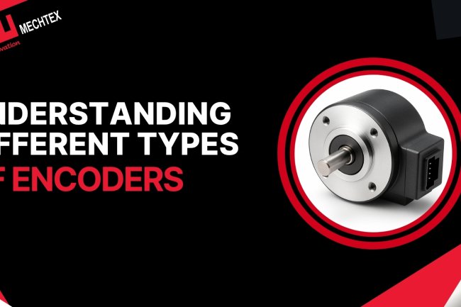
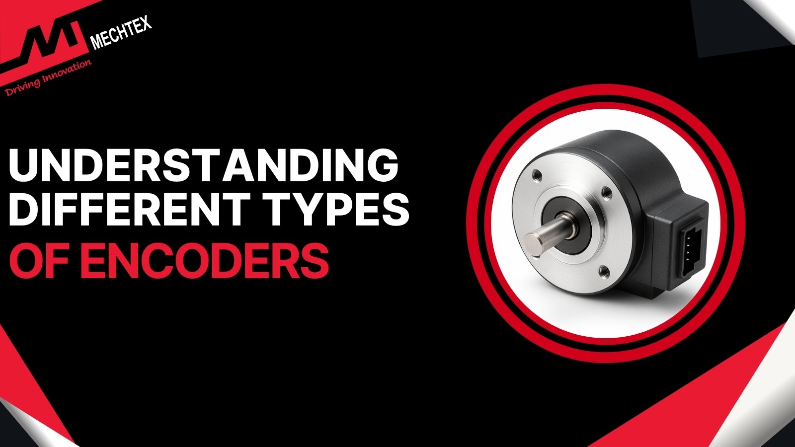
Understanding Different Types of Encoders
How Does a Magnetic Encoder Work?
A magnetic encoder works with the help of magnetic field variation and magnetic sensors. These sensors convert the mechanical movement of the motor into electrical signals.
Components of a Magnetic Encoder
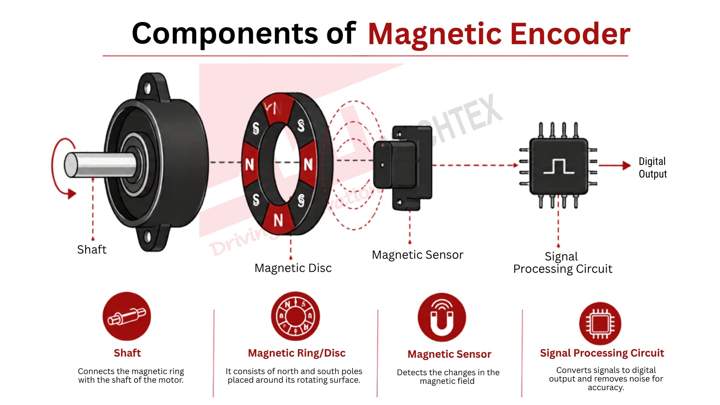
A magnetic encoder consists of various sensing and signal-processing components. When the motor starts rotating, these components sense the variations in the magnetic field and convert them into electrical signals for accurate feedback.
Let's get a detailed understanding of the components of a magnetic encoder:
- Magnetic Ring/Disc
It consists of north and south poles placed around its rotating surface. These magnetic poles produce the variation in the magnetic field due to continuous shaft movement.
- Magnetic Sensor
When the magnetic ring/disc starts rotating, the magnetic sensor detects the changes in the magnetic field and converts them into electrical signals.
- Signal Processing Circuit
This circuit processes the electrical signals and converts them into a digital output. It also increases the signal’s accuracy by removing the electrical noise and other parameters during the processing.
- Shaft
It connects the magnetic ring of the encoder with the shaft of the motor. When the motor rotates, it indicates to the encoder to start its sensing process.
Step-by-Step Signal Generation
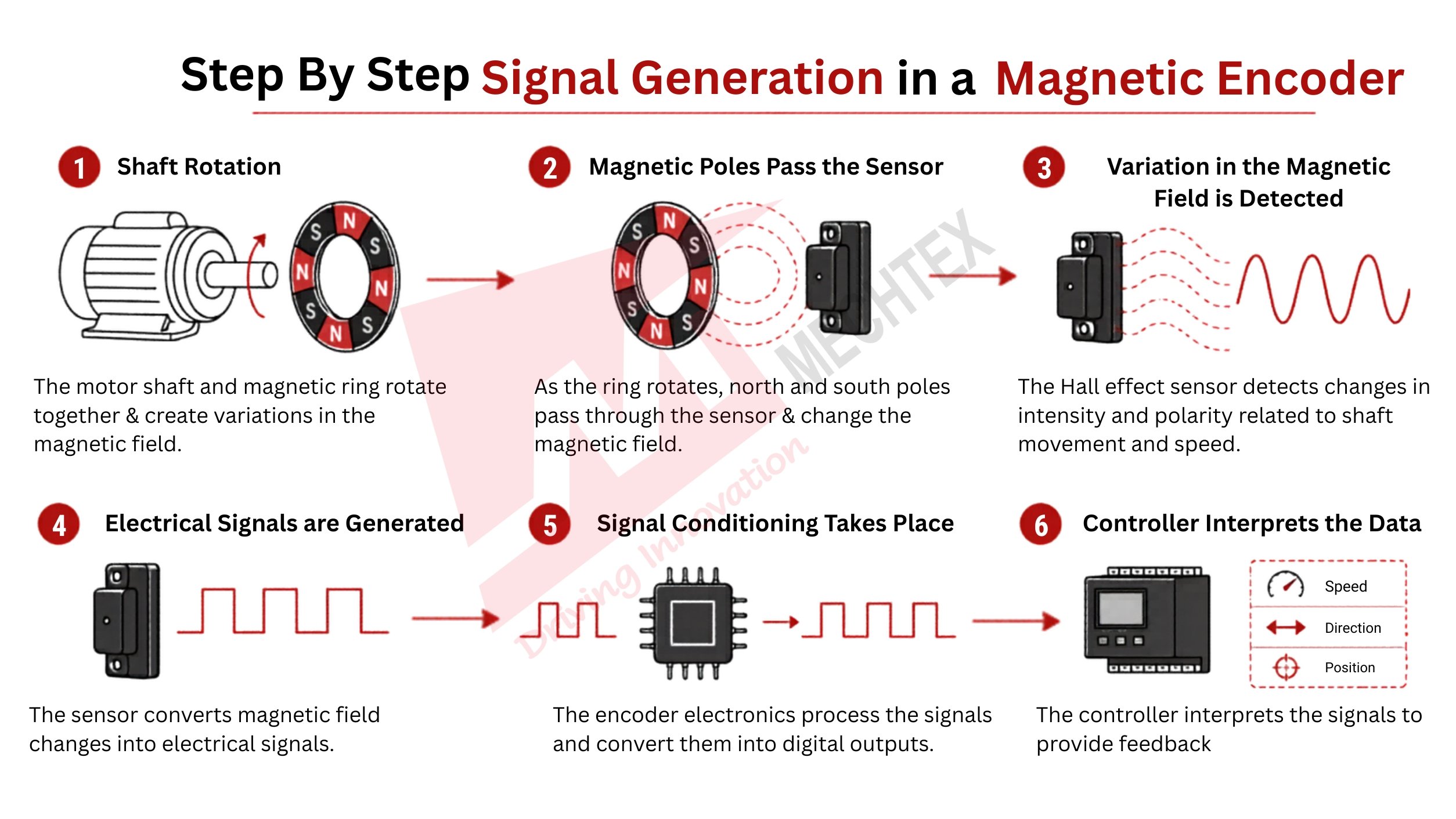
- Shaft Rotation
When the motor starts its rotation, the magnetic ring connected to the shaft of the motor also rotates in parallel to it. These movements produce the variations in the magnetic field produced around the sensor.
- Magnetic Poles Pass the Sensor
When the magnetic ring rotates, both north and south poles pass through the magnetic sensor. The magnetic sensor continuously monitors the changes in the magnetic field that occur due to magnetic poles.
- Variation in the Magnetic Field is Detected
The Hall effect sensor detects the changes in the intensity and polarity of the magnetic field. These changes are directly related to shaft movement and the rotational speed of the motor. When the speed of the motor is high, the changes in the intensity and polarity of the magnetic field will also be high. While at low speed, the magnetic field experiences a low change in intensity and polarity.
- Electrical Signals are Generated
The sensor converts the changes that appear in the magnetic field into electrical signals. The frequency of the electrical signal depends on the encoder’s resolution and its rotational speed.
- Signal Conditioning Takes Place
The electronics of the magnetic encoder convert the electrical signals into the digital outputs. These digital outputs establish communication between the motor and controller for efficient operation.
- Controller Interprets the Data
The controller interprets the electrical signals into feedback about the speed, direction, and movement of the motor. It is the real-time feedback that helps to control the movement of the motor.
Why Magnetic Encoder Works Where Optical Encoder Fails
The working of an optical encoder heavily depends on the light transmission. When the light emits on the rotating disc of the encoder, the photosensor detects the light pattern and converts it into electrical signals for motion data. When dust, oil, or particles interfere with the light, they block the visual for the photosensor and provide less accurate data about the movement.
In a magnetic encoder, when the magnetic field changes due to the poles of a magnet, the sensor detects the changes and converts them into electrical signals for more accurate data. Dust, oil, and particles cannot affect the working of the magnetic encoder and provide more accurate feedback than the optical encoder.
Understanding Quadrature Output (Channel A, B, Z)
Quadrature output is a type of signal commonly used by incremental encoders. This signal detects the movement, speed, and direction of the motor and provides feedback with high accuracy.
In this signal, the incremental encoder produces two types of output, mainly called "Channel A" and "Channel B." By monitoring the timing of both channels, the controller detects the shaft movement and rotation of the motor and provides data. Sometimes, the incremental encoder uses a third channel called “Z” for reference positioning.
What are Channel A and Channel B?
Channel A and Channel B are square wave signals produced by the incremental encoder. Both these channels generate the same number of pulses. But these signals are generated in phases and shifted to 90 degrees with every shaft movement. Therefore, this signal/output is called “quadrature output."
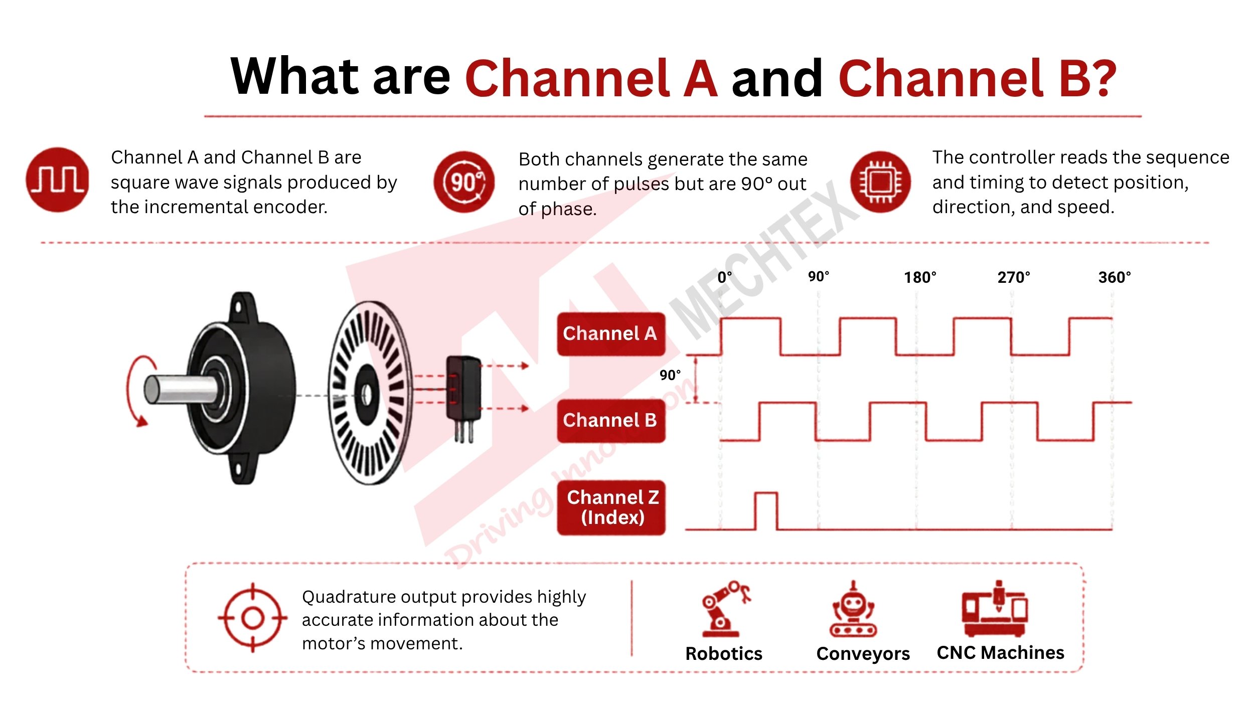
As the encoder’s shaft moves, the pulses quickly switch between High and Low states. The controller detects the sequence and timing of these pulses and measures the motor’s movement. These signals also detect the rotational speed of the motor by counting the pulses and their frequency and provide accurate feedback.
Image
Quadrature output (Channels A, B, and Z) provides highly accurate information about the electric motor’s movement and is used in servo systems, robotics, and CNC Machines.
How Direction is Determined
The direction of the motor is detected by identifying which channel leads the other during the pulse generation.
For example, if channel A changes its position before channel B, the controller identifies the rotation of the motor as a clockwise rotation. On the contrary, if channel B changes its state before channel A, the controller detects the rotation as an anticlockwise rotation.
This relationship between these channels (Channel A & B) helps the controller to identify the direction of the motor. By continuously monitoring this relationship between the channels (Channel A & B), the motion control system responds immediately to changes in motion and provides feedback on them.
What is Channel Z (Index Pulse)?
The channel Z produces one pulse for every shaft rotation. One complete shaft rotation = One Pulse. Unlike channels A and B, which produce pulses continuously, channel Z produces one pulse for each rotation of the shaft at a fixed angle.
The channel Z acts as a reference point and is used to reset the calibration and position of the encoder. The controller uses this channel Z as a starting point during the start-up.
Frequently Asked Questions
Q1. How does an encoder determine the direction of rotation?
An encoder determines the direction of rotation with the help of the phase difference between Channel A and Channel B. If Channel A leads Channel B, the encoder detects that the motor is rotating in a clockwise direction. If Channel B leads Channel A, the encoder determines it is the anticlockwise direction of the motor.
Q2. What is the difference between PPR and CPR?
PPR means Pulses Per Revolution. It refers to the number of pulse cycles an encoder generates during one shaft rotation. CPR means Counts Per Revolution. It refers to the total count of pulses identified by the controller after processing quadrature signals. Since a controller can identify both the rise and fall of signals, CPR is usually higher than PPR.
Q3. Why does an absolute encoder not need homing after power loss?
An absolute encoder provides a unique digital code for every position of the motor. It allows the controller to identify the exact position of the motor immediately after power is restored. Unlike an incremental encoder, it restores the motor position from the unique code, so the system does not require homing.
Q4. Can an encoder work without a controller?
No. An encoder only identifies the position, speed, and direction of the motor and generates electrical signals. The controller converts these signals into motion data. Without a controller to process the electrical signals from the encoder, it is not possible to determine the exact position, speed, and direction of the motor.
Q5. What is the difference between an optical encoder and a magnetic encoder?
An optical encoder uses a slotted disc and LED lights to detect the speed, direction, and position of the motor. A magnetic encoder detects the speed, direction, and position of the motor by sensing variations in the magnetic field around a magnetic disc.