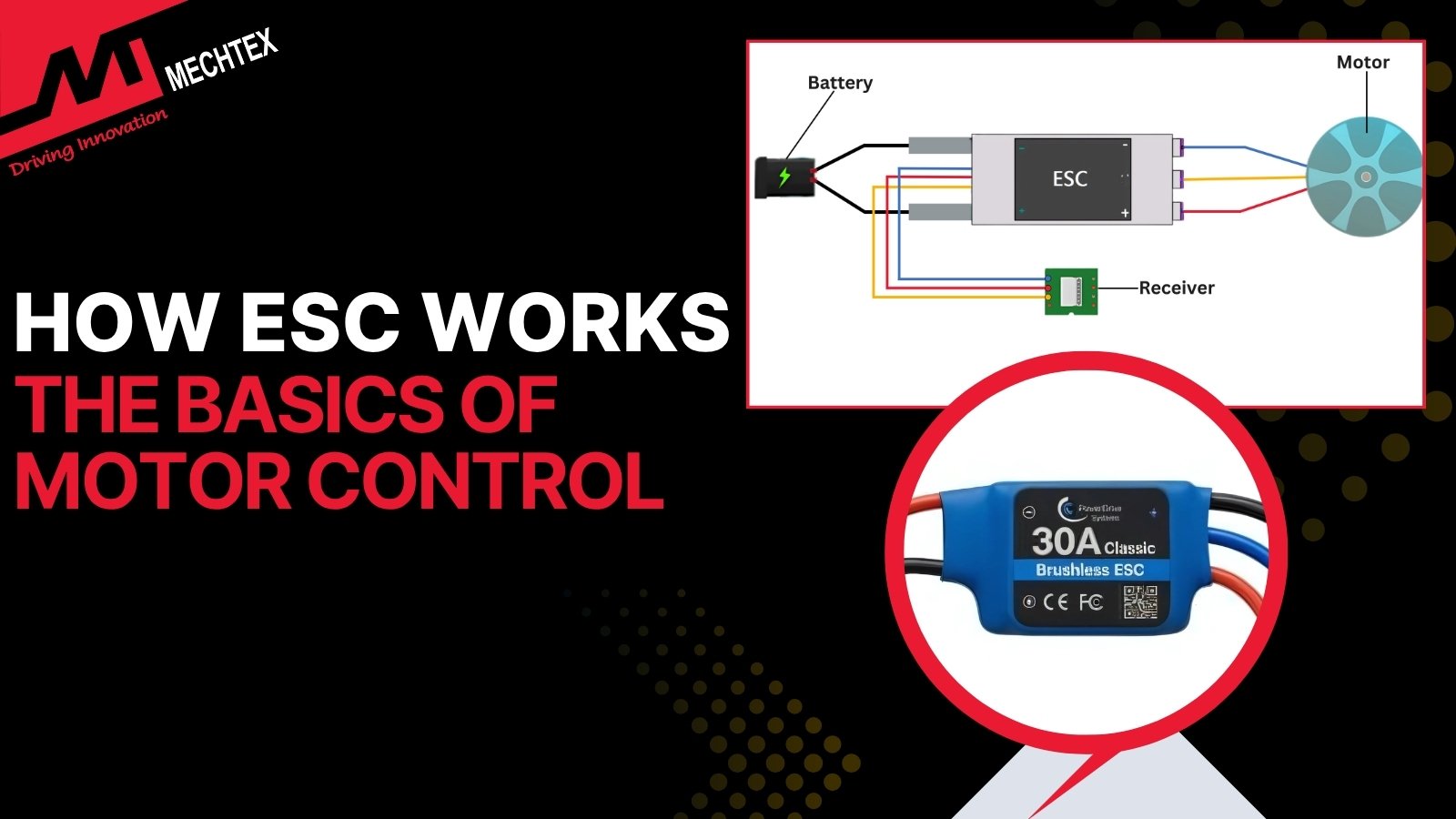
How ESCs Work: The Basics of Motor Control
An electronic speed controller (ESC) is a crucial device that controls the speed, direction, and braking of an electric motor. Its operation is rooted in power electronics and digital signal processing to enable precise motor control with real-time responsiveness.
In the rapidly growing world of robotics, drones and based on user electric mobility, the Electronic Speed Controller (ESC) has emerged as a crucial component in motor control systems.
Whether it’s powering a drone, driving an electric vehicle, or operating a robotic actuator, the ESC plays a vital role in ensuring smooth, efficient, and responsive motion.
In this blog, we will explore the fundamentals of ESC, its working, and how it interacts with brushless motors to deliver precise control over speed and direction.
What is an Electronic Speed Controller (ESC)?
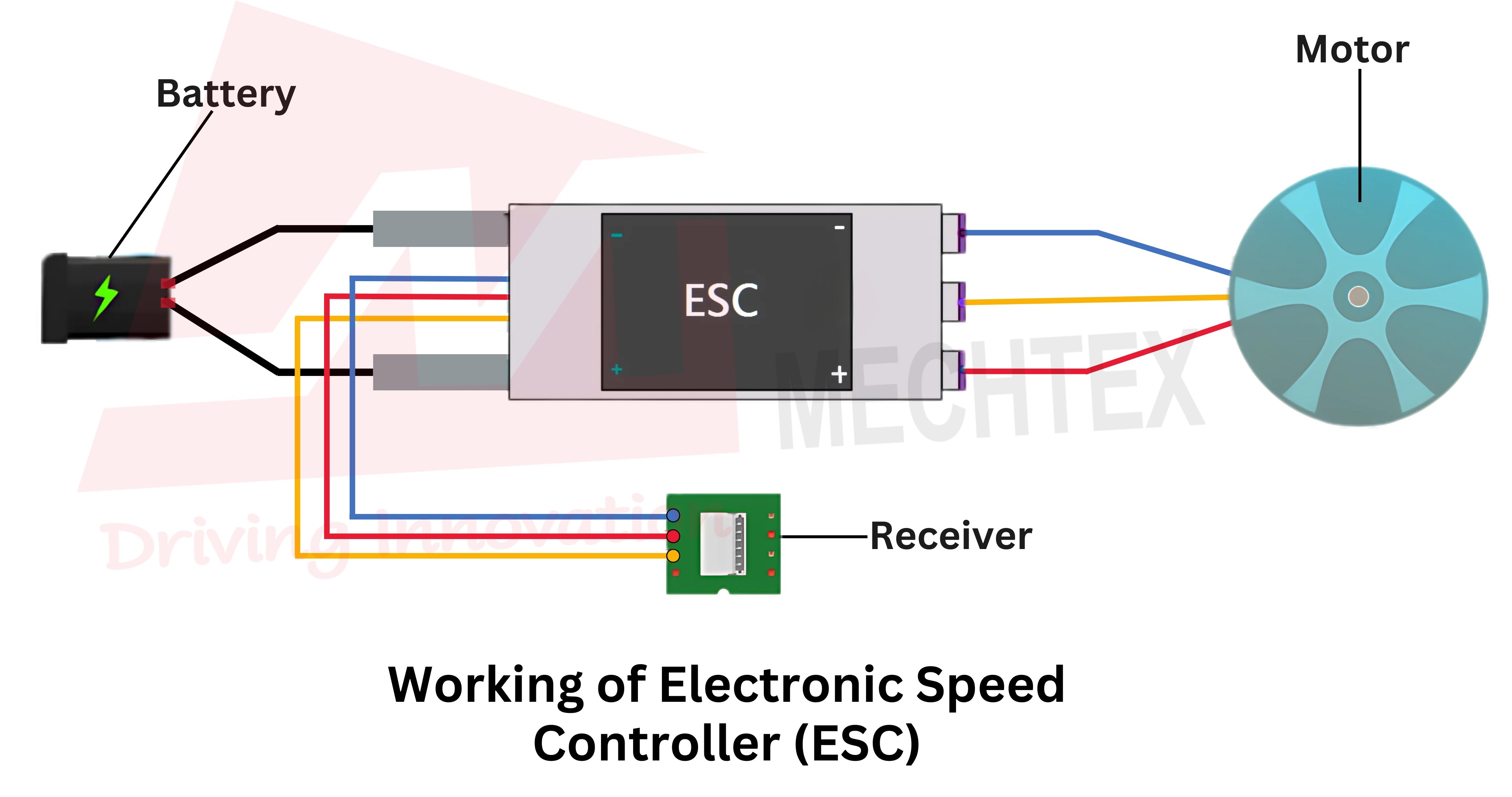
An electronic speed controller (ESC) is an essential component used in electric-powered systems such as drones, RC vehicles, e-bikes, and robotics to manage the speed and direction of the electric motor. It acts as a bridge between the power source (battery) and the motor to ensure smooth and precise operation based on user input or programmed instructions.
ESCs are typically designed for two types of motors - Brushed DC motors and Brushless DC motors. In drone applications, brushless ESCs are widely used for their efficiency, reliability and light weight.
ESC works by converting the DC voltage from the battery into a modulated signal (using PWM) to control motor speed. The controller receives signals from the flight controller, throttle, and transmitter to adjust the power of the motor.
Watch the YouTube Video by "Painless360" to learn some basics about ESCs.
It ensures that the motor runs at a desired speed, maintains stability, and responds promptly to changes in commands. It comes in various current ratings and sizes, allowing users to select one that matches their electric motor and application requirements.
In summary, an ESC plays a vital role in controlling motor dynamics, improving system efficiency, and protecting components from electrical stress, making it indispensable for modern electric propulsion systems.
Also Read: What is PWM in an ESC? | Pulse Width Modulation Explained
How ESCs Work?
An electronic speed controller (ESC) is a crucial device that controls the speed, direction, and braking of an electric motor. Its operation is rooted in power electronics and digital signal processing to enable precise motor control with real-time responsiveness.
At its core, ESC starts by receiving the pulse width modulation (PWM) signal from the flight controller or transmitter. This signal contains the speed command, which the ESC interprets and converts into high-power signals suitable for driving the motor.
The ESC modulates the DC power from the battery using high-frequency switching of MOSFETs to regulate the voltage and current sent to the motor.
For Brushless DC motors, ESCs use a three-phase output, which carefully time the switching of current through the motor windings to create a rotating magnetic field. This field interacts with the permanent magnets in the rotor and causes it to rotate.
The timing of the switching of the current is either controlled via sensorless techniques, such as back-EMF or sensor-based feedback, hall sensor, to ensure smooth and synchronised commutation.
For Brushed DC gear motors, the process is simple. The ESC adjusts the duty cycle of the PWM signal applied to the electric motor terminals to effectively control the voltage and speed without switching phases.
Modern ESCs also incorporate microcontrollers and firmware, which allows features like soft-start, overcurrent protection, temperature monitoring, low-voltage cutoff, regenerative braking, and telemetry.
It not only enhances motor performance and efficiency but also protects the system from damage due to overloading and overheating.
Step-by-Step Guide: How an Electronic Speed Controller (ESC) processes the throttle signal.
An Electronic Speed Controller (ESC) works as a brain for both the controller and motor. It receives a throttle signal from the controller and converts it to power supplied to an electric motor for rotation.
Let’s see a step-by-step process on how the ESC (Electronic Speed Controller) uses the throttle signal for rotation.
1. Throttle Input Received
The Electronic Speed Controller (ESC) gets a throttle signal from the flight controller, RC controller, or other control systems. This signal indicates to the ESC (Electronic Speed Controller) about how fast an electric motor will rotate.
The throttle signals are usually sent as a PWM, Dshot, or other similar communication method, depending upon the application’s requirement.
2. Signal Interpretation
Every Electronic Speed Controller (ESC) consists of a microcontroller. This microcontroller detects the throttle signal received from the flight controller and converts it to the speed command for an electric motor.
A low signal from the microcontroller means the motor will rotate at a slow speed, while a high signal means the motor will rotate at a high speed (100% speed).
The microcontroller also verifies whether the received throttle signal is valid or not, within the operating range or not, to avoid any failures.
3. Power Calculation
Depending on the throttle signal, the Electronic Speed Controller (ESC) decides the voltage, current, and switching frequency required for an electric motor to achieve the desired speed.
It also calculates the amount of power required by an electric motor for smooth and efficient operation.
4. PWM Signal Generation
The Electronic Speed Controller (ESC) generates a Pulse Width Modulation (PWM) signal by quickly switching the power between ON & OFF to control the speed of the motor.
It also maintains the PWM (Pulse Width Modulation) signals to regulate the power supplied to the motor for smooth, continuous rotation.
5. Electronic Commutation
Unlike conventional DC motors, BLDC (Brushless DC) Motors use an Electronic Speed Controller (ESC) for commutation. It energises the motor windings in a particular sequence for continuous movement in the correct direction.
6. Feedback and Adjustments
The Electronic Speed Controller (ESC) continuously monitors the speed and direction of the motor and regulates the power supply for stable operation.
Today, Many Modern ESCs (Electronic Speed Controllers) also monitor the current, voltage, and temperature of the motor to avoid sudden failures.
7. Continuous Motor Rotation
Finally, the ESC (Electronic Speed Controller) supplied the correct amount of power to the motor for rotation at the desired speed and torque.
When the throttle changes, the ESC repeats the same process for smooth and continuous operation.
Key Parameters Controlled by ESCs
An Electronic Speed Controller (ESC) manages multiple parameters to ensure efficient, smooth, and safe operation of electric motors. These key parameters include:
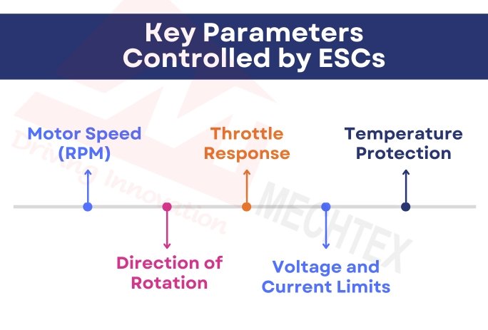
- Motor Speed (RPM)
The primary function of the ESC is to regulate the motor's speed based on input commands. It does this by adjusting the duty cycle of the PWM signal to control the voltage applied to the motor.
- Direction of Rotation
ESCs can change the direction of the motor by altering the energising sequences of motor windings. This is crucial in applications like drones, where reversing thrust enables quick directional changes.
- Throttle Response
ESCs manage how quickly the motor reacts to input challenges, which allows for smooth acceleration and deceleration based on programmed throttle curves.
- Voltage and Current Limits
Advanced ESCs monitor input voltage and output current to protect against over-voltage, under-voltage, and overcurrent conditions that could damage the system.
- Temperature Protection
Built-in temperature sensors allow ESCs to prevent overheating by reducing power or shutting down when thermal limits are exceeded.
Brushed ESC vs Brushless ESC: How Working of ESCs differ
An Electronic Speed Controller (ESC) regulates the speed, direction, voltage, and current and enhances the overall performance of an electric motor. However, its working depends upon the type of motor: Brushed DC Motor or Brushless DC motor.
ESCs for brushed DC motors operate with the help of simple switching methods, while ESCs for brushless DC motors require advanced commutation for continuous operation.
Let’s deep dive into the differences between ESC for brushed DC motors and ESC for brushless DC (BLDC) motors:
1. Commutation Method
- Brushed DC Motor ESC: It uses simple switching methods, as brushes and commutator regulate the current inside the brushed DC motor. This makes the Electronic Speed Controller design simple for basic applications.
- Brushless DC Motor ESC: It switches the current between the BLDC motor windings in a particular sequence and performs electronic commutation for rotation. It precisely switches the current into the windings for efficient operation.
2. Number of Wires
- Brushed DC Motor ESC: It typically connects with 2 wires, one wire for positive current and the other wire for negative current. Its wiring configuration is simple, which makes the installation and integration with the motor easy.
- Brushless DC Motor ESC: It uses 3-phase wires to control the speed of the BLDC motor. This 3-phase wire configuration results in precise phase control for efficient operation.
3. Control Complexity
- Brushed DC Motor ESC: It has a simple control circuit, as the motor’s rotation does not require timing for synchronisation. Therefore, speed control is mainly achieved by regulating the voltage and PWM (Pulse Width Modulation) signals.
- Brushless DC Motor ESC: It has advanced control algorithms and systematic logic, as motor windings require current in a particular sequence. It also continuously adjusts the switching sequence to regulate the speed and torque as per the conditions.
4. Detect Rotor Position
- Brushed DC Motor ESC: It does not require detecting the rotor’s position, as brushes automatically switch the current between the windings. It reduces sensor dependency and design complexities.
- Brushless DC Motor ESC: It detects the rotor position with the help of hall sensors to switch the current between the motor windings in a particular sequence. It is essential for a smooth start and continuous performance.
5. Efficiency & Performance
- Brushed DC Motor ESC: It provides basic speed control and low efficiency due to friction and wear. It also experiences high energy loss due to the mechanical contact of brushes and commutator inside the motor.
- Brushless DC Motor ESC: It offers high efficiency, speed stability, fast response, and smooth control over the speed and torque of the BLDC motor. It makes Brushless DC (BLDC) motors ideal for high-performance applications.
ESC Firmware and Protocols
ESC can run on various firmware options depending on the applications. Some popular open-source and commercial firmwares are:
Popular ESC Firmware Options
- BLHeli / BLHeli_S / BLHeli_32
Widely used in high-performance systems requiring fast responses, such as PV drones, RC vehicles, robotics, and aerial cinematography platforms. These firmwares offer smooth throttle response and motor timing control.
- SimonK
This firmware is known for its simplicity and efficiency. SimonK is ideal for small UAVs, educational robotics kits, and hobby-grade applications that prioritise the ease of setup and reliability.
- VESC (Vedder ESC)
A highly configurable open-source firmware designed for electric skateboards, e-bikes, robotics, industrial automation, and research projects. VESC supports advanced control methods.
Common Communication Protocols
- PWM (Pulse Width Modulation)
The most widely used protocol for RC systems, robotics, and basic industrial motor control. Simple to implement, but may have latency compared to the modern alternatives.
- Oneshot125 / Oneshot42 / Multishot
It is a high-speed analogue protocol that offers lower latency than PWM. Ideal for flight controllers in drones, fast-response servo systems, and RC vehicles.
- DShot (Digital Shot)
A digital signal protocol offering precise control without requiring calibration. It is used in racing drones, precision robotics, CNC systems, and other latency-sensitive applications.
- CAN / UART / I2C
Digital series commutation interfaces are common in industrial automation, autonomous systems, research platforms, and smart ESC systems.
Conclusion
ESCs are the backbone of modern electric motion systems. They bridge the gap between digital control signals and raw electrical power, offering precise and reliable motor control. Whether you're flying a drone, powering a robot, or designing an electric vehicle, understanding how ESCs work is essential to unlocking optimal performance.
From basic speed regulation to sophisticated sensor feedback systems, ESCs continue to evolve, fueling innovation across industries.
Also Read: What is PWM in an ESC? | Pulse Width Modulation Explained
Frequently Asked Questions
Q1. How does ESC know the position of the rotor?
An Electronic Speed Controller (ESC) uses many methods, depending on the motor type, to detect the rotor position. In a sensored brushless motor, it uses a Hall effect sensor to detect the rotor position for smooth operation. In a sensorless brushless motor, it uses the back-EMF technique to detect the rotor position and is suitable for high-speed applications.
Q2. What is the difference between a sensored and a sensorless ESC?
A sensored ESC (Electronic Speed Controller) uses Hall sensors to detect the rotor's position even at standstill condition, which results in precise current flow in motor windings. A sensorless ESC (Electronic Speed Controller) uses the back-EMF technique to detect the rotor's position even at high speed.
Q3. Why does ESC (Electronic Speed Controller) beep on power on?
ESC (Electronic Speed Controller) does not have its own display, therefore it uses the electric motor as a speaker to communicate system updates. During startup, a single beep repeating every second indicates the ESC (Electronic Speed Controller) is powered ON and working properly. Unusual beeping during startup means a missing signal or protocol mismatch.
Q4. What causes an ESC (Electronic Speed Controller) to fail during operation?
The most common cause of ESC failure is when a stalled motor sends a sudden current spike to the MOSFETs and damages them. Other causes include voltage spikes, current surges, and incorrect wiring, which damage MOSFETs, gate drivers, and capacitors inside the ESC (Electronic Speed Controller).
Q5. What is dead time in ESC (Electronic Speed Controller) and why does it matter?
Dead time is a tiny pause (50 to 2000 nanoseconds) between the switching of one MOSFET and another in the same phase. Dead time is necessary because if both MOSFETs work simultaneously in the same phase, it results in a short circuit and damages the ESC (Electronic Speed Controller).