Torque-Speed Characteristics of DC Gear Motors: A Complete Analysis
The torque-speed curve of a DC motor is a fundamental characteristic that illustrates the relationship between the DC motor’s output torque and rotational speed. It helps engineers understand how the DC Gear motor performs under varying loads.
DC gear motors are integral parts of modern automation solutions such as robotics, conveyor belts and other motion control solutions. By combining a DC motor with a gearbox, they deliver high torque at reduced speed. A critical aspect of understanding and utilising DC gear effectively lies in analysing their torque-speed characteristic.
In this blog, we will provide you with a complete breakdown of the relationship between torque and speed of the DC gear motor, how gearboxes influence its relationship, and what engineers must consider for optimal performance of the motor.
What is DC Gear Motor?
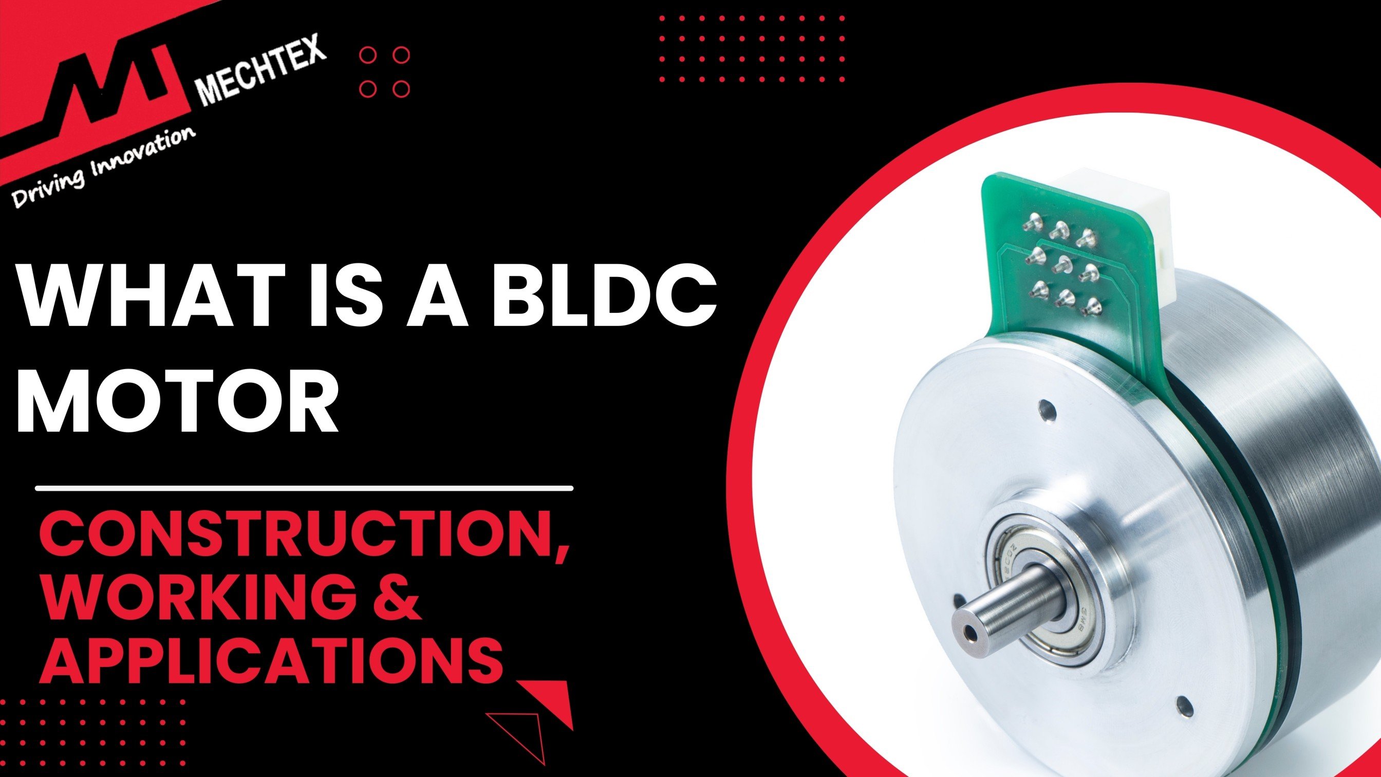
A DC gear motor is an integrated electromechanical device that combines a DC motor with a gearbox to deliver high torque at low speed.
The DC motor provides the rotational energy, while the gearbox reduces the motor’s speed and increases its torque. There are two types of DC gear motors: brushed DC gear motors and brushless (BLDC) gear motors.
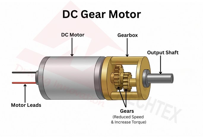
Brushed motors are simple and cost-effective, but have high wear and tear due to friction. Brushless motors offer long life, high efficiency, and less maintenance.
Gear ratios within the gearbox determine the speed and torque balance. A higher gear ratio provides greater torque but low speeds, while lower gear ratios does the opposite. DC gear motors typically feature planetary, spur, or worm gear configurations, chosen based on torque density, efficiency, and size constraints.
Key advantages of DC gear motors include compactness, precise speed control, easy integration, and cost efficiency. This makes the DC gear motors suitable for driving mechanisms that require substantial force, such as conveyor belts, robotic arms, solar panel trackers, and cleaning robots.
Also Read
Torque-Speed Curve of a DC Motor
The torque-speed curve of a DC motor is a fundamental characteristic that illustrates the relationship between the DC motor’s output torque and rotational speed.
This curve is essential for engineers to understand the motor’s performance under different mechanical loads to ensure proper motor selection for specific applications.
In a typical DC motor, the torque-speed relationship is inversely proportional and linear. As the load torque increases, the DC motor’s speed decreases. Conversely, at no load, the motor operates at its maximum speed but produces zero torque. When the load is so high that the motor cannot rotate, the motor reaches its stall torque, which is the maximum torque it can deliver at zero speed.
This linear nature can be mathematically expressed as:
T = Tstall ( 1- N/Nno-load)
Where,
T = torque at speed N
Tstall = stall torque
N = motor speed
Nno-load = No load speed
Key Points of the Torque-Speed Curve
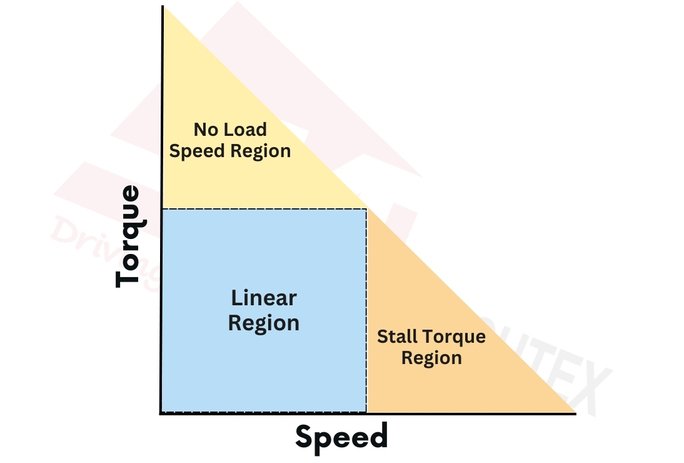
No load Speed
- The motor runs at its highest speed with no mechanical load.
- No torque is generated.
- The current draw is minimal, just enough to overcome internal losses.
Stall Torque
- The maximum torque motor can produce.
- Speed = 0 RPM.
- The current drawn is maximum, which can damage the motor if sustained.
Linear Region
- Between no-load speed and torque.
- This is the practical operating range of the motor.
- Motor efficiency and power vary across this region.
Interpreting Practical Torque-Speed Graphs
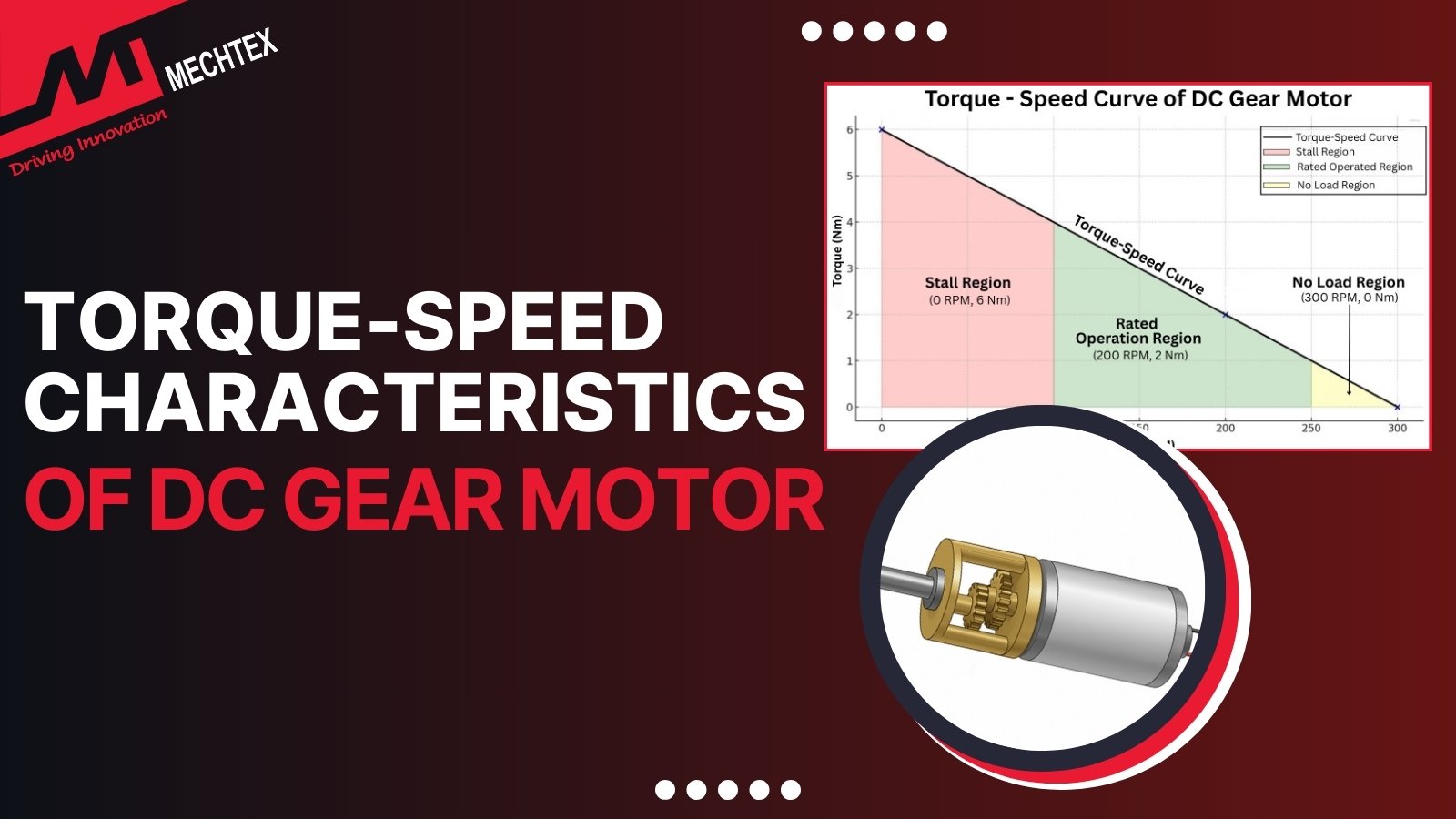
In real-world applications, the torque-speed graph of a DC gear motor helps engineers understand how the motor performs under varying loads. Unlike idealised linear graphs, practical torque-speed characteristics consider real-world constraints such as efficiency, heat dissipation, and safe operating limits.
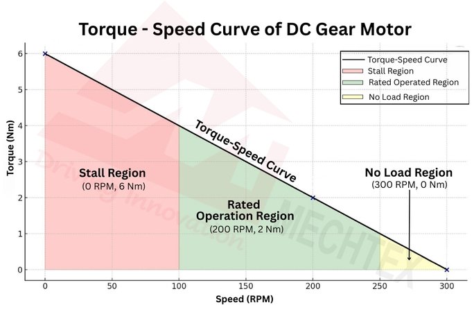
Starting Torque (Stall Torque)
- At this point, the DC motor draws maximum current and produces maximum torque when starting from rest.
- Example: In our case, stall torque = 6 Nm, meaning the motor can exert this force before it starts turning.
Rated Torque (Continuous Safe Operating Torque)
- It is the recommended torque at which the DC motor runs efficiently for long periods without overheating.
- Example: Our motor has rated torque = 2 Nm and rated speed = 200 RPM, ensuring reliable operation.
Peak Torque (Short Duration Overload Capacity)
- Some DC motors can exceed the rated torque briefly, but it is a risk of overheating and damage.
- Peak torque is higher than rated torque, but should only be used for short bursts.
Speed Range
The DC gear motor speed varies linearly with torque from no-load speed to stall torque.
Example:
- No-load speed = 300 RPM (0 Nm torque)
- Rated speed = 200 RPM (2 Nm torque)
- Stall torque = 6 Nm (0 RPM)
- Gearboxes modify this range by increasing torque while decreasing output speed.
Key Factors Influencing Torque-Speed Characteristics of DC Gear Motors
The torque-speed behaviour of a DC gear motor is shaped by multiple electrical, mechanical, and environmental factors. Understanding these helps in accurate motor selection and system design. The key factors influencing torque speed characteristics are:
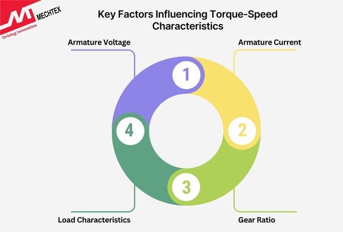
- Armature Voltage
The speed of a DC motor is directly influenced by the applied armature voltage. When the voltage increases, the no-load speed also increases, effectively shifting the torque-speed curve upward.
- Armature Current
Torque in a DC motor is proportional to the armature current. As the current increases, torque also increases. However, excessive current can lead to overheating and eventual damage.
- Gear Ratio
The gearbox attached to a DC motor changes its output torque and speed. A higher gear ratio decreases output speed while increasing the torque. This mechanical transformation modifies the motor’s torque-speed characteristics to better suit load requirements.
- Load Characteristics
Different loads affect the torque-speed curve in different ways. Resistive loads result in a linear reduction in speed with an increase in torque. In variable load, where the torque demand rises with speed, it distorts the curve. Rapid load changes can push the motor outside its optimal operating range.
Conclusion
Torque-speed characteristics are a foundational concept in the design and application of DC gear motors. By understanding how torque and speed are interrelated—and how this relationship shifts with the addition of a gearbox—engineers and designers can make informed choices for reliable and efficient performance. Whether you're building a robot, automating a production line, or designing compact actuators, a deep grasp of torque-speed dynamics ensures that your motor solution delivers exactly what the application demands.