V Curve of Synchronous Motor: Armature vs Field Current & Power Factor
Discover how V curves help analyze synchronous motor behavior. See how armature current changes with field excitation and how power factor moves from lagging to leading.
Synchronous Motors are widely used in various applications due to their ability to maintain constant speed under various load conditions. These motors operate at synchronous speed with the frequency of supply which offers precise speed control and enhances the performance of the motor. One of the critical aspects of understanding and optimising the performance of the synchronous is the V Curve. It is the graphical representation of the motor’s armature current and field excitation.
The V curve of a synchronous motor provides insights to optimise the performance of synchronous motors and helps engineers improve the efficiency and power factor of the motor. In this blog, we will dive into the concept of the V curve, understand its significance, how it is derived, and how it practically helps applications in industrial settings.
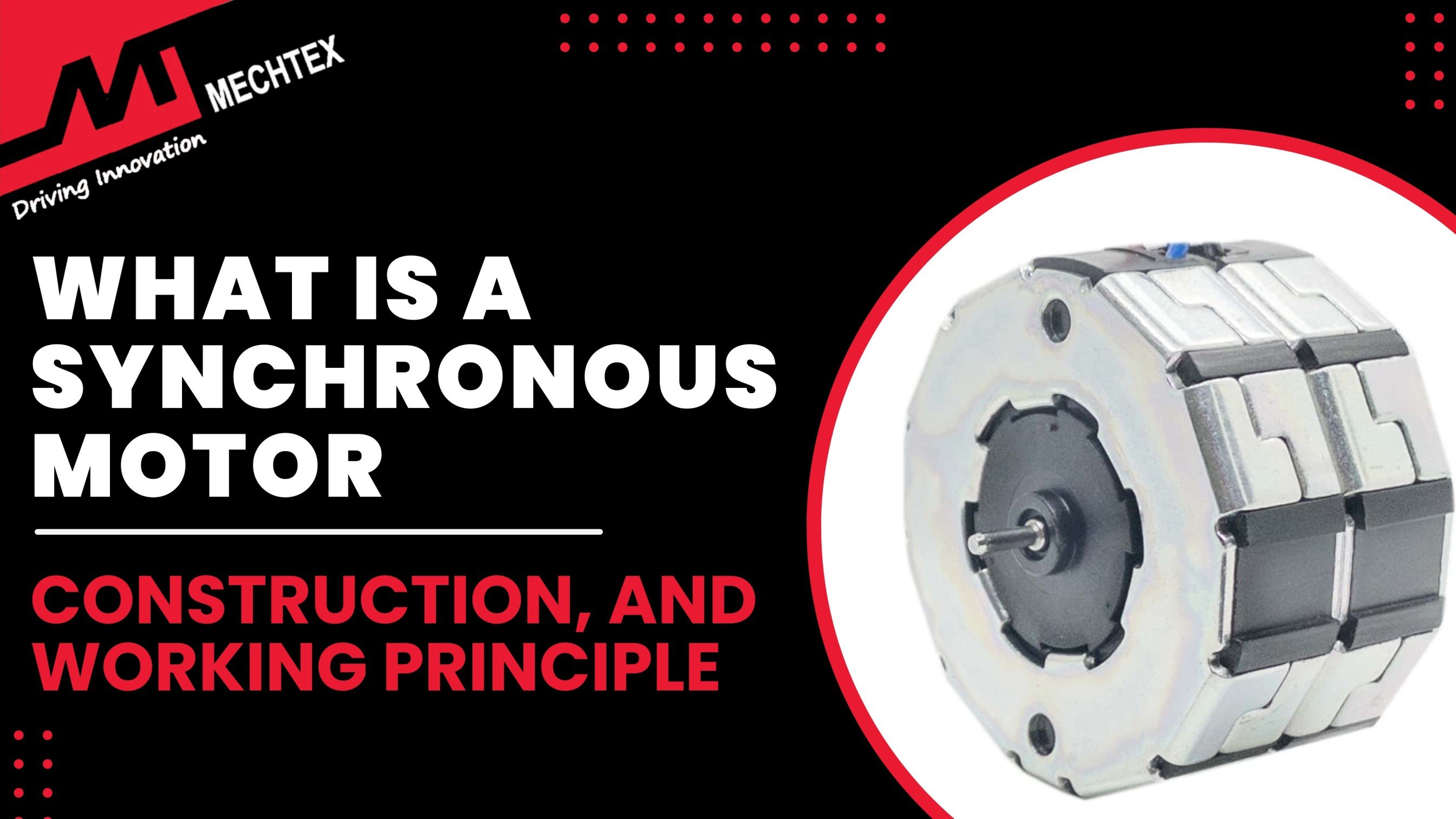
What is a Synchronous Motor?
Before diving into the concept of the V curve of synchronous motors, it is necessary to understand the basics of synchronous motors. A synchronous motor is a type of AC motor that operates at constant speed. The rotation of the shaft of the synchronous motor is synchronised with the frequency of the current supply. It means the motor’s speed remains constant regardless of variations in load.
The construction of a synchronous motor consists of two main components: stator and rotor. Stator is the stationary part of the motor. It consists of electromagnets and produces a magnetic field. Rotor is a rotating part of the motor. It consists of a permanent magnet and interacts with the magnetic field of the stator.
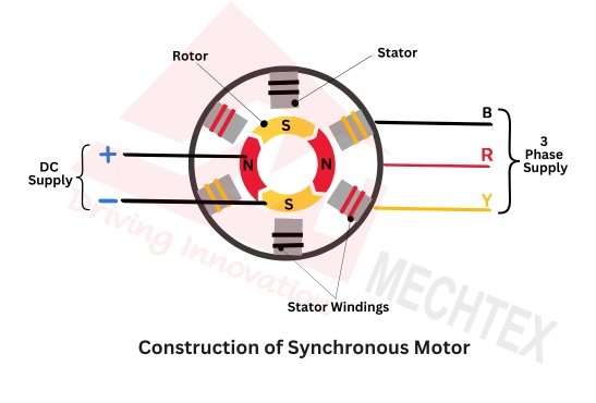
The working of the synchronous motor depends upon the frequency of the AC supply. The stator is connected to the AC supply and generates the rotating magnetic field. Meanwhile, The rotor is connected to the DC supply, creates a steady magnetic field and interacts with the stator. It is known as field excitation, which is crucial for synchronous motor operation.
As the stator magnetic field rotates, it pulls the rotor magnetic poles along with it and causes it to rotate. Unlike induction motors, which rely on slip between the stator's rotating field and the rotor. The synchronous motor's rotor rotates at exactly the same speed as the stator’s field with the help of field excitation.
Also Read
What is a Synchronous Motor| Construction, Working Principle and Applications
The Role of Field Excitation
The field excitation refers to the process where the DC is supplied to the rotor winding to produce the necessary magnetic field that locks with the stator magnetic field and thereby maintains synchronisation to ensure smooth and stable operation.
There are different levels of field excitation that directly impact the synchronous motor’s power factor and its efficiency. Three important levels of field excitation are:
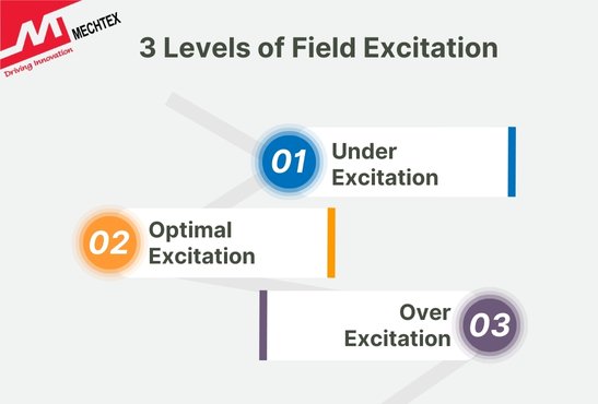
- Under Excitation
When the field excitation is below the optimal level, it is known as under-excitation. In this condition, the synchronous motor operates at a lagging power factor which leads to higher losses and reduced efficiency.
- Optimal Excitation
When a synchronous motor is operating at unity power factor, which minimises the current and improves the overall efficiency of the motor. This condition is known as optimal excitation. It is crucial in the V curve and represents the most efficient operating condition for the synchronous motor.
- Over Excitation
When the field excitation is above the optimal level it is known as over-excitation. In this condition, the synchronous motor operates at the leading power factor, which leads to overheating and potential failures.
Also Read
The Role of Excitation Systems in Synchronous Motors
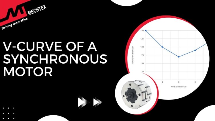
V Curve of Synchronous Motor
V curve is an important concept to understand the relationship between the motor’s armature current (la) and field excitation (lf) under various load conditions to control and maintain the synchronous speed of the synchronous motor.
To create the V curve of the synchronous motor, first, the synchronous motor’s field excitation (lf) is varied at various levels, while keeping the load constant and corresponding to the armature current (la) of the motor. Then armature current (la) is measured at each level of field excitation.
When the field excitation (lf) is increased from a low value, then the armature current (la) decreases and reaches a minimum point. Then again it starts to increase and reaches the highest point, it forms a V curve.
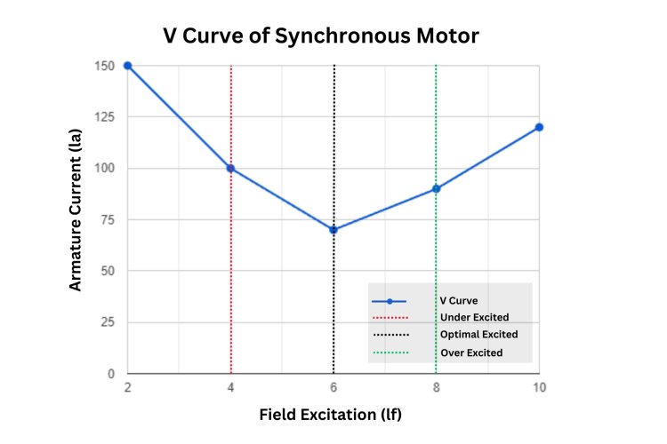
For example, a synchronous motor with a constant load of 50 KW. As the field excitation (lf) is increased from 2A to 10A, the armature current then decreases and reaches a minimum point and then starts to increase.
Let's understand with the following measurements,
lf = 2A, la = 150A
lf = 4A, la = 100A,
lf = 6A, la = 70A (This point represents the minimum armature current)
lf = 8A, la = 90A,
lf = 10A, la = 120A
Where,
lf = Field Excitation
la = Armature Current
The above V curve graph helps in determining the optimal field excitation for minimal armature current, which corresponds to the most efficient operation of the synchronous motor.
In the above example, the minimum point on the V-curve is at If = 6 A, where Ia is at its lowest, 70 A. This indicates that the synchronous motor is operating at its most efficient state, neither under-excited nor over-excited, which is referred to as the “unity power factor”.
Beyond this point, increasing or decreasing the field excitation causes the armature current to increase, which can lead to less efficient operation and possible heating issues in the motor windings.
The above-resulted graph is typically divided into three regions: under-excited, optimally excited, and over-excited.
- Under Excited Region
On the left-hand side of the V curve, where field excitation is low, the synchronous motor is under-excited. In this region, the magnetic field produced by the rotor is not sufficient to fully interact with the stator magnetic field which leads to lagging power factor, increased losses and reduced efficiency of the motor.
- Optimal Excited Region
At the bottom of the V curve, lies the point of optimal excitation. In this region, the synchronous motor operates most efficiently with minimal armature current and maximum torque per ampere. This is the ideal operating condition for most synchronous motors.
- Over-Excited Region
On the right-hand side of the V curve, where field excitation is high, the synchronous motor is over-excited. In this region, the synchronous motor operates at the leading power factor, which can be beneficial in some cases as it reduces reactive power. However, similar to the under-excited condition, the armature current begins to rise again as the field excitation increases, which can lead to potential issues such as overheating and mechanical stress if not carefully managed.
Conclusion
The V curve of synchronous is not just a graphical representation, it is an in-depth analysis for optimising synchronous motor performance, and efficiency and ensuring reliable operation in various applications. By understanding this V curve, engineers can enhance the synchronous motor’s operation to achieve the desired efficiency and power factor.
In the modern industrial world, where efficiency and reliability are necessary, the V curve remains a fundamental concept that helps in maximising the performance of synchronous motors.