What are Reduction Gears | Introduction, Types and Reduction Ratio Calculation
Reduction gears are mechanical devices that decrease speed and increase torque. They use gear ratios to achieve the desired output.
What is a Gearhead?
Reduction gearheads use the concept of gear reduction which implies that the gears reduce the speed of the machine but increase its torque. They are usually made of steel, hardened metal, nylon, plastic, or rubber gear. The usage of sintered gears is also increasing to decrease the expense of gear production. These are self-lubricating. They are available with a variety of mounting options, reduction ratios, and output shafts.
Types of Reduction Gearheads
Just like there are different types of tools for different jobs, there are also different types of gearheads for different needs.
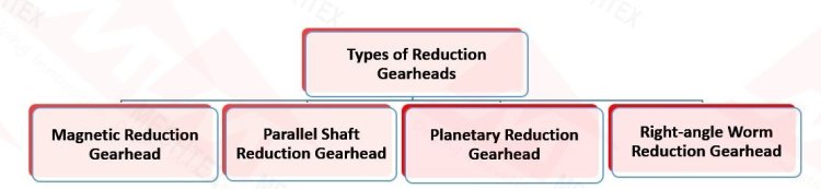
Here are some of the most common types of reduction gearheads
- Single Reduction Gearhead
The single reduction gearhead consists of one pair of gears. It consists of ports via which the engine and propeller shafts enter the arrangement. A small-sized gear, called the pinion, directly runs a gear that is connected to the propeller shaft.
- Double Reduction Gearhead
The double-reduction gearhead is mostly used in applications where very high speeds are required. In this arrangement, a small gear, called a pinion, is anchored on the input shaft allowing a flexible coupling. The pinion is attached to an intermediate part known as the first reduction gear.
- Magnetic Reduction Gearhead
The magnetic reduction gearheads, also called magnetic gear reducers, can beneficially replace the conventional gear reducers to provide torque and speed control. This arrangement works on the principle of magnetic attraction instead of physical contact between the shifting components. Complicated assembly, lower torque, and heavy weight have slowed the diffusion.
The magnetic reduction gearheads eliminate the need to lubricate and hence have a low maintenance cost. Since there is no requirement for lubrication, the machines can run in an extreme temperature range of -200° C to 350º C.
- Parallel Shaft Reduction Gearhead
The parallel shaft reduction gearhead consists of a multiple-gear assembly. This arrangement enhances the system reduction. The entire gear reduction ratio is defined by enhancing each gear ratio from every gear part.
If the pinion and its anchoring part have the same number of teeth, then reduction does not take place. In this case, the gear ratio is 1:1. The gear is used as an idler whose main function is to change the rotation direction and not decrease or increase the speed or torque, respectively.
- Planetary Reduction Gearhead
The gear ratio in the planetary reduction gearhead depends on the number of teeth of the ring gears and the sun ring gears. The planet gears function as idlers and do not affect the gear ratio. The planetary gear ratio is the summation of the number of teeth on the ring and sun ring gears divided by the number of teeth on the sun ring gear.
- Right-angle Worm Reduction Gearhead
The right-angle worm reduction gearhead depends on the count of teeth on the mating worm wheel and the count of threads or starts on the worm.
Also Read
Planetary Gearbox | Introduction and Construction
What is the Reduction Ratio
The gear reduction ratio is calculated to determine the speed and output torque of the system. It measures how many revolutions an input gear takes to make one revolution of the output gear. This ratio is expressed in fractions or decimals with the number of teeth of the input gear and with the number of teeth of the output gear.
It is important to maintain the efficiency of the gear system. It helps to select the right gear size and configuration to achieve the desired speed and torque of the system. Change in gear ratio affects the efficiency and performance of the system. Therefore it is essential to carefully calculate the reduction ratio for a system.
How to calculate the reduction ratio
To calculate the reduction ratio, one must know the number of teeth on both the input gear and output gear of the gear system. After calculating the number of teeth, the ratio can be calculated by dividing the number of teeth on the input gear by the number of teeth on the output gear.
Here's the formula:
Gear Reduction Ratio = Number of teeth on Input Gear/Number of teeth on Output Gear
For Example -
If the input gear has 10 teeth and the output gear has 20 teeth, the gear reduction ratio would be 1:2 or 0.5 as a decimal. This means that for every one revolution of the input gear, the output gear will make two revolutions.
Reduction Logic
Reduction Logic likely relates to the thought process involved in selecting and utilizing a gearhead to achieve a desired reduction in speed and increase in torque. The following calculation needs to be considered while selecting a reduction gearhead
- Ratio Calculation
The gear ratio, also known as the reduction, is obtained by dividing the number of teeth on the larger gear by the number of teeth on the smaller gear.
- Torque Calculation
Mo = Mir
where,
Mo = output torque (Nm)
Mi = input torque (Nm)
r = gear transmission ratio
- Power Calculation
Po = Pi
where,
Po = output power (W)
Pi = input power (W)
Factors To Consider While Selecting Reduction Gearheads
Selecting the right reduction gearhead isn't just about picking the fastest or strongest one. It's a Strategic alignment between power and precision, where you need to choose the perfect gearhead for your project.
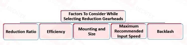
From desired speed and torque to size and efficiency, every factor plays a role in this gearhead. So please consider the following factors while selecting a reduction gearheads
- Reduction Ratio:
Decide the desired reduction level based on your motor speed and target output speed. Higher ratios transmit to slower output speeds and higher torque. Single-stage gearheads offer simplicity but limited reduction, while multi-stage reduction gearheads provide greater reduction but they are more complex and expensive as compared to single-stage gearheads.
- Efficiency
The efficiency is mostly dependent on the number of trains. It is a mean value that is measured at a surrounding temperature of 20º C to 25º C. A newly bought gearbox will show lower values. These values will however reach the normal values post the run-in period.
Metal body spur gearboxes are commonly used in gearboxes for their durability and ability to maintain consistent performance under demanding conditions, ensuring long-term reliability and efficiency.
- Mounting and Size:
Choose a reduction gearhead with a mounting configuration that suits your motor and application (e.g., flange, foot mount). Also, Consider the available space and weight constraints in your project when selecting a reduction gearhead. Its Compact options are ideal for applications where space is limited.
- Maximum Recommended Input Speed
The maximum recommended input speed has a great impact on the noise level and the lifetime of the gearhead. Depending on the application, it should be taken into consideration while deciding the reduction ratio.
- Backlash
Backlash is the angle at which a gearhead output shaft can rotate freely with a blocked input. It occurs mostly due to gear play which is necessary to avoid jamming. It can also occur due to shaft play and elastic deformation of the teeth and shafts under load.
Spur gearboxes are commonly used in applications where precise positioning is required, and minimizing backlash is critical for maintaining the accuracy and efficiency of the system.
Advantages
Reduction gearheads offer various advantages for your applications, whether you're an engineer designing industrial machinery or robotics. Here are some key advantages:
- Higher torque output
- Speed reduction
- Higher resolution
- Can drive large inertial loads
- Shorter positioning time
- Downsize
- Improved damping characteristics
- Increased axial and radial load
- Increased rigidity
- Longer life
- Less maintenance required
Disadvantages
As Reduction gearheads offer various advantages for your applications, also there are some disadvantages it. Here are some drawbacks of reduction gearhead
- The gear operation is noisy.
- They are not favourable for greater velocities.
- They are not favourable for transmitting motion over a large distance.
- No flexibility.
- May get permanently damaged on excessive loading.
Applications
Reduction gearheads are used in a diverse range of applications, from robotics to heavy machinery. Here are some applications where reduction gearheads:
- Lifter
- Construction
- Tank fabrication
- Security Camera
- Mining industry
- Conveyors
- Crushers
- Cooling towers
- Agitators
- Elevators
- Extruders
- Filters
Do you want a perfect balance between the speed and torque of a motor for your application? Mechtex reduction gearheads are the perfect solution for you. We have various types of gearheads such as planetary gearheads, spur gearheads, parallel shaft gearheads and many more. If you want your application to work in a controlled manner, purchase our planetary gearhead and spur gearheads. We provide tailor-made gearboxes as per customer needs.