Components of ESC (Electronic Speed Controller): MOSFETs, Gate Driver, Microcontroller, and Softwares
An ESC (Electronic Speed Controller) consists of various hardware and software components such as MOSFETs, Gate Driver, Microcontrollers, Sensors, and Communication Protocols. It is a complete component breakdown guide with a diagram.
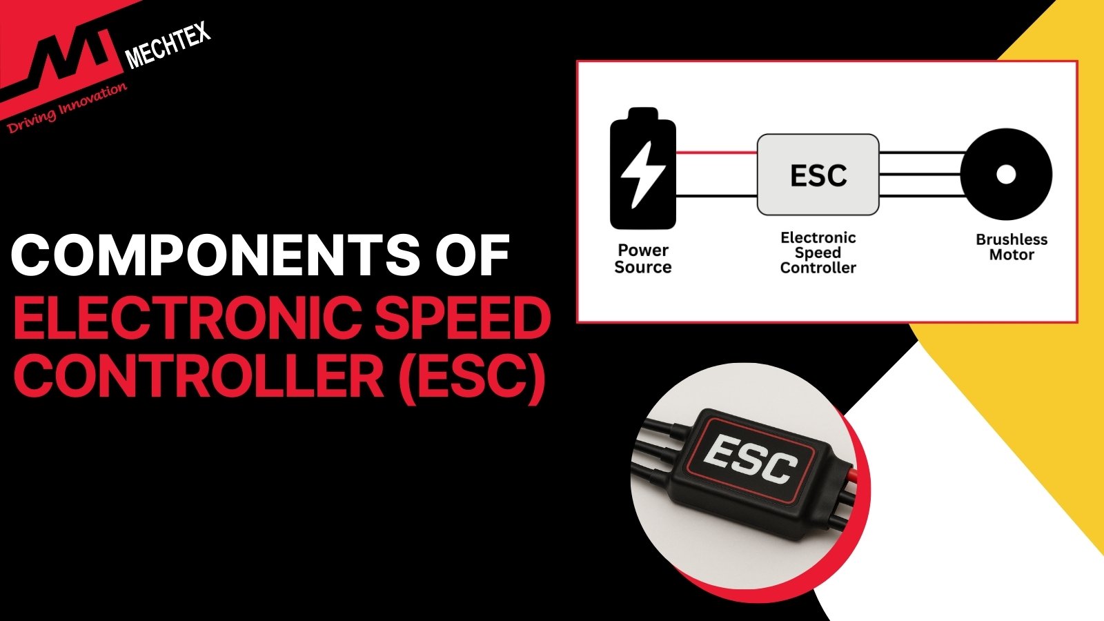
Components of ESC (Electronic speed controllers): Hardware & Software Components
An ESC (Electronic Speed Controller) is a device which control the speed, direction, and braking of the electric motor. It receives the signals from the motor controller to adjust the power supply to the motor. It mainly used for BLDC (Brushless DC Motor) and Brushed DC Motor for smooth and efficient operation.
An Electronic Speed Controller (ESC) consists of various hardware and software components which help to control the motor and provide accurate motion data. Understanding the components of ESC helps the engineers and professionals to select the right ESC (Electronic Speed Controller) for their applications.
In this blog, we have explained all the major components of ESC, their functions, and explained how they interact with the system for efficient operation. We also cover the different components of ESC used for various applications.
Hardware Component of ESC (Electronic Speed Controller)
The hardware components of the ESC form the foundation of its operation. They manage power delivery, signal conversion, and protection to enable smooth communication with the motor and controllers. The following are some major hardware components of ESC:
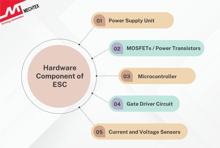
- Power Supply Unit
The ESC is powered directly by the battery, which ranges from low-voltage LiPo cells to high-voltage systems.
To ensure reliable operation, a voltage regulator or BEC is used to step down and provide a steady low-voltage DC supply for microcontrollers.
BEC refers to Battery Eliminator Circuit. It supplies a regulated low-voltage power supply to the external sources such as receivers, flight controllers, and sensors without any external power source.
It converts the battery voltage supply into a stable DC output, especially 5V and 12V, depending on the application requirements.
Its main function is to simplify the wiring of the ESC (Electronic Speed Controller) and improve power management to ensure smooth and reliable operation of the ESC.
Additionally, the capacitors are placed at the input stage to smooth the sudden voltage spike and minimise electromagnetic interference (EMF). It protects both the controller and the electric motor from noise and vibrations.
This arrangement ensures that the ESC can deliver stable and uninterrupted power for smooth motion.
- Microcontroller
The microcontroller serves as the brain of an ESC. It executes the software algorithms that manage communication, speed regulation, and thermal protection.
In real time, it manages the timing and power supplied to the electric motor within microseconds for continuous operation.
Most commonly used microcontrollers in ESCs are the ARM Cortex-M series, dsPIC, or STM32. All these microcontrollers are used for high-speed processing, low latency, and managing advanced algorithms of BLDC (Brushless DC) motors.
These microcontrollers consist of a PWM technique for precise signals, ADC input for monitoring current and voltage, and multiple communication protocols to handle telemetry, diagnose, and program efficiently.
- MOSFETs / Power Transistors
The power stage of an ESC is made by using MOSFETs for low- to medium-sized power systems and IGBTs for high-power systems.
IGBTs manage high-voltage and high-current supplies without any other parallel device. But it has a slow switching speed than MOSFETs, which makes it unsuitable for high-frequency applications.
Both serve as an electronic switch to regulate current flow into motor windings in proper sequence.
In ESC, there is a three-phase inverter bridge made up of six MOSFETs with two transistors dedicated to each motor phase.
To ensure high efficiency and low resistance, MOSFETs are used, as they minimise conduction loss and heat generation.
Also Read: How ESCs Work: The Basics of Motor Control
- Gate Driver Circuit
The gate driver circuit is an important link between microcontrollers and MOSFETs in an ESC.
While a microcontroller generates low-voltage control signals, MOSFETs require higher voltages and rapid transitions to switch current effectively.
The gate driver amplifies these signals to the necessary levels and ensures fast and precise switching.
It provides both high and low side drive capability for each motor phase to enable proper communication.
- Current and Voltage Sensors
ESCs rely on feedback for safe and precise motor control. Current sensors, such as Hall effect sensors, are used to monitor current to prevent overcurrent.
Many budget-friendly ESCs (Electronic Speed Controllers) use shunt resistors as an alternative to hall sensors. It is simple in configuration and cost-effective to measure the current.
Voltage sensors, such as dividers, are used to track battery voltage and back-EMF for speed regulation and protection. Back-EMF sensing detects the rotor position with the help of the voltage available in unpowered motor windings. It enables sensorless commutation and allows the ESC to switch the current smoothly.
- Thermal Management
An ESC (Electronic Speed Controller) produces heat during high-current switching and continuous motor operation. It makes thermal management necessary in the ESC (Electronic Speed Controller) for smooth and reliable performance.
Heat sinks, thermal pads, cooling fans, and copper PCB layers are components used in ESCs to eliminate the heat from MOSFETs.
Temperature sensors, such as NTC, also continuously monitor the temperature of the internal components. It detects the overheating and allows the microcontroller to enable thermal protection.
It prevents component failure, improves efficiency, and provides stable and continuous performance under demanding conditions.
Software Components of an ESC
Hardware components alone cannot control complex motor dynamics. The real intelligence of an ESC lies in its software algorithms. Some key software components are:
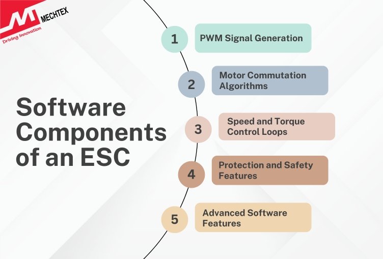
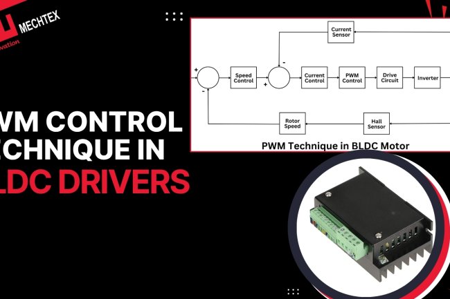
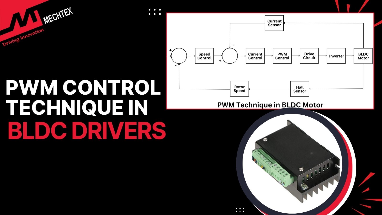
- PWM Signal Generation
Pulse Width Modulation (PWM) is the core technique used in ESCs to control speed, torque and other dynamics of the motor. The microcontroller (MCU) generates a duty cycle, which defines how much voltage is applied to the motor phase.
A higher duty cycle means higher voltage and higher speed, while a lower duty cycle means lower voltage and lower speed.
Advanced ESCs often employ Space Vector PWM (SVPWM), which enhances efficiency and ensures smooth torque output.
SVPWM (Space Vector Pulse Width Modulation) is an advanced PWM technique that efficiently switches the inverter’s power transistors and produces a rotating voltage vector.
Unlike the Sinusoidal PWM technique, SVPWM mathematically calculates the switching states of the inverter, which results in 15% higher DC bus voltage utilisation.
It also reduced harmonic distortion, provided better efficiency, and improved the overall performance of the motor.
Also Read: What is PWM in an ESC? | Pulse Width Modulation Explained
- Motor Commutation Algorithms
ESC is a software that uses commutation methods to switch the current into the appropriate motor winding in synchronisation to estimate the rotor position.
There are two types of commutation methods: Sensor-based commutation and sensorless commutation.
Sensor-based commutation methods use Hall sensors and encoders to detect the rotor position. The hall sensors detect the position of the rotor and send it to the ESC (Electronic Speed Controller).
Using this information, the Electronic Speed Controller switches the current between the phases of the motor to regulate the speed and torque of the motor and improve the performance of the application.
Sensorless Commutation is a method used to control the movement of a BLDC (Brushless DC) motor. This method eliminates the use of hall sensors and uses electrical signals, such as back-EMF generated within the BLDC motor, to detect the rotor position.
The sensorless commutation method is used in applications such as drones, fans, pumps, and other industrial equipment where high efficiency is essential.
It uses various advanced techniques, such as Kalman observers or Sliding-Mode observers, to detect rotor position.
One of the most common sensorless techniques is the Zero-Crossing Detection Technique. In this method, the ESC (Electronic Speed Controller) continuously monitors the unenergized phase of the motor to know when back-EMF signals cross this phase of the motor.
By detecting this point and timing, the ESC (Electronic Speed Controller) determines the rotor’s position and performs the next commutation step.
- Speed and Torque Control Loops
ESC use a closed-loop control method to regulate motor speed and torque with precision.
Feedback signals are compared against the reference value and adjust the PWM signal accordingly.
In advanced ESCs, Field-Oriented Control (FOC) decouples torque and flux to enable highly accurate and efficient control.
- Protection and Safety Features
ESC software consists of fault-handling protocols to safeguard the motor, battery and controller during operation.
Protection includes overcurrent and short circuit protection to prevent component damage, while the overheating shutdown protects MOSFETs and circuitry from thermal failure, and soft starts minimise mechanical stress during operation. In certain applications, regenerative braking is also used to recover energy.
- Advanced Software Features
Advanced ESC software goes beyond basic motor control and enables smart and adaptable performance.
Techniques like adaptive timing control optimise efficiency at different speed ranges, while sensor fusion algorithms combine data from multiple sources to improve rotor position estimation.
These advanced software enhance efficiency, adaptability and future-proofing ESC technology.
- Communication Protocols
Communication Protocols are methods used by the Electronic Speed Controller (ESC) to transmit the data/information about the motor and its movement to the external devices such as flight controllers, Microcontrollers (MCUs), and other onboard systems.
These protocols help the ESC (Electronic Speed Controller) to receive information about the motor’s speed, direction, and position and transfer it to the external devices to improve the motor's performance.
It also transfers telemetry information of the motor, such as RPM, voltage, and speed, and directly impacts the response time and accuracy of the motor.
Some Common ESC protocols are PWM protocol, Oneshot protocol, Multishot protocol, DShot protocol, UART protocol, CAN, and CAN FD protocol.
ESCs (Electronic Speed Controller) for Different Applications
Electronic Speed Controllers (ESCs) are designed differently for each application. Their design depends upon the application’s performance, their operating environment, and control needs.
ESCs used in drones are light in weight, provide instant switching frequencies, and rapid response towards signals to ensure smooth and stable flight. ESCs used in EVs (Electric Vehicles) have the capacity to handle high voltage and current loads while ensuring efficiency, precision, and reliability.
Therefore, the components of ESC (Electronic Speed Controllers), such as MOSFETs, communication interfaces, and firmware algorithms, differ significantly as per the application's requirements.
| Specification | Drone ESC | EV ESC | Robotics ESC |
|---|---|---|---|
| Voltage Range | 7.4V – 60V (2S–14S LiPo) | 48V – 800V+ | 12V – 120V |
| MOSFET Type | Low-RDS(on), high-speed switching MOSFETs | High-current MOSFETs or IGBTs/SiC MOSFETs | Precision-control MOSFETs with efficient thermal design |
| Communication Protocol | PWM, OneShot, MultiShot, DShot | CAN, CAN FD, UART, Ethernet | CAN, CANopen, EtherCAT, UART |
| Cooling Method | Airflow from propellers, heat sinks | Liquid cooling, forced-air cooling, large heat sinks | Heat sinks, forced-air cooling |
| Key Firmware Feature | Fast throttle response and sensorless commutation | Advanced FOC, regenerative braking, battery management integration | Precise position, speed, and torque control with closed-loop feedback |
The choice of ESC depends upon various factors such as power level, precision, communication method, and operating condition. Selecting the right ESC type for the applications ensures optimal performance and improves functionality.
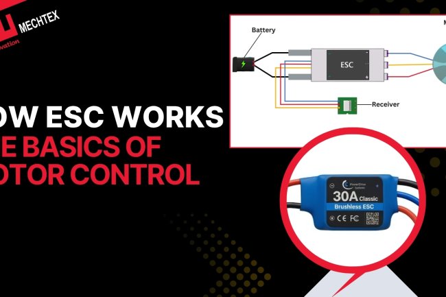
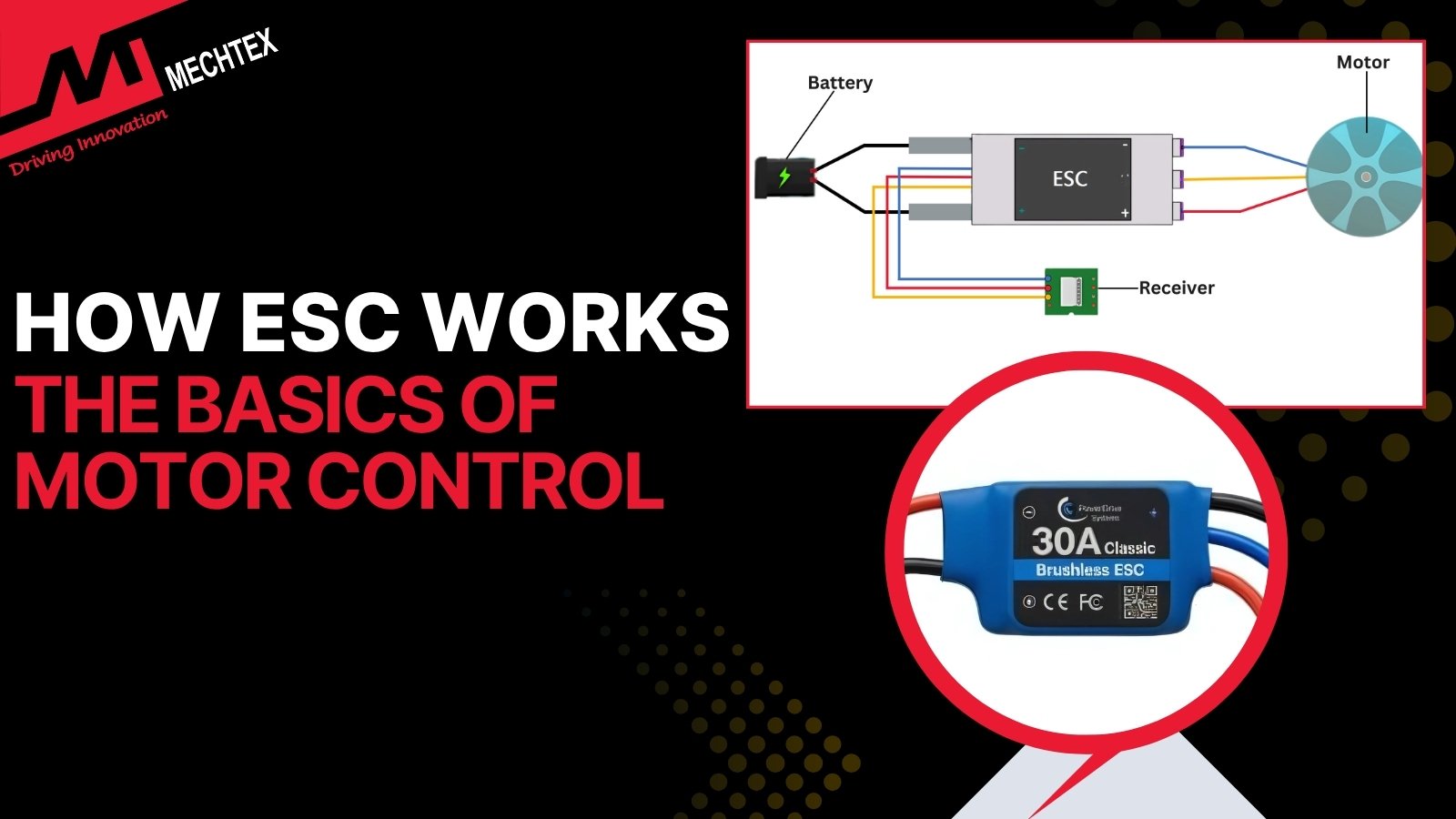
How ESC (Electronic Speed Controller) Works Together
Every component of ESC (Electronic Speed Controllers) works together in a real-time system to detect the movement of an electric motor.
The Microcontrollers (MCUs) receive the throttle signals from the flight controller, convert them into PWM signals, and send them to the gate driver. The gate driver uses these PWM signals to switch the MOSFETs and energise the motor windings in a proper sequence.
Simultaneously, the current sensors monitor the current load, the back-EMF detects the rotor’s position, and thermal sensors send the thermal data to firmware algorithms to avoid failures.
"For a complete step-by-step guide on how ESC components work, read our dedicated blog - How ESCs Work: The Basics of Motor Control → "
Frequently Asked Questions
Q1. What is the most important component in an ESC (Electronic Speed Controller)?
The Microcontroller (MCU) is the most important component in an ESC (Electronic Speed Controller). It works as the brain of an ESC. It receives commands from the flight controller, processes them into electrical signals, and sends them to the algorithm. It also manages the commutation methods and coordinates with other components, such as sensors, electronics, and communication interfaces, for efficient and reliable control.
Q2. What is BEC in an ESC (Electronic Speed Controller)?
The Battery Elimination Circuit (BEC) is a built-in voltage regulator in an ESC (Electronic Speed Controller). It converts the battery voltage into a stabilised voltage (5V or 6V) and supplies it to external devices such as flight controllers and microcontrollers. It eliminates the need for a separate battery and reduces the overall weight and cost of the system.
Q3. What is the difference between a Sensored ESC and a Sensorless ESC?
Sensored ESCs (Electronic Speed Controllers) use Hall sensors or encoders to detect the rotor's position and provide continuous feedback on it. Sensorless ESCs (Electronic Speed Controllers) use techniques such as back-EMF and Kalman observers to detect the rotor's position. They eliminate the need for Hall sensors and ensure optimal performance with high precision.
Q4. What causes an ESC (Electronic Speed Controller) to overheat?
An ESC (Electronic Speed Controller) can overheat due to various factors, such as excessive current draw, an inadequate cooling system, poor ventilation, rapid acceleration and deceleration, and operating beyond rated limits. Continuous overheating affects its performance and damages its internal components, which can lead to complete failure.
Q5. What is the role of firmware in an ESC (Electronic Speed Controller)?
Firmware is the intelligence layer placed between the hardware components of an ESC and the motor control system. The microcontroller is a hardware processor, and the firmware is the software that runs inside the MCU — both work together to operate the ESC. Firmware receives input signals from the flight controller and converts them into PWM signals. It also monitors different types of sensors, such as current sensors and thermal sensors, and enables protection functions such as overcurrent protection and thermal shutdown to prevent failures.
Conclusion
An ESC is far more than a power-switching device. It is a sophisticated combination of hardware components (MOSFETs, gate drivers, sensors, processors, protection circuits) and software algorithms (commutation, PWM control, sensorless estimation, fault handling). Together, they provide reliable, efficient, and precise motor control across industries.
Understanding the key components of an ESC gives insights into why these devices are indispensable in drones, EVs, robotics, and automation. As motor control technology advances, future ESCs will feature even more intelligent algorithms, higher efficiency power devices, and smarter communication systems—pushing the boundaries of performance.