Closed‑Loop Speed Control in BLDC Motors: PI, PID & State Feedback
Closed-loop control is a feedback-based control method, where motor speed is continuously monitored and compared with predefined reference speed to maintain a desired torque and speed under varying load conditions. It has three main techniques - PI Controller (Proportional-Integral) or PID (Proportional-Integral-Derivative) controller, and State Feedback Controller.
Brushless DC Motors (BLDC motors) have become an indispensable component in modern motion control systems due to their efficiency, reliability, long life, and dynamic response.
However, achieving precise speed control and stable torque, especially under varying load conditions, requires a speed control technique. This is where the closed-loop speed control technique comes into play.
In this blog, we will explore the fundamentals, implementation of closed-loop speed control techniques, and three main control strategies: PI, PID, and State Feedback.
What is Closed-Loop Speed Control?
Closed-loop control is a feedback-based control method used in electric motors to maintain a desired speed under varying load conditions.
In the closed-loop control technique, the motor speed is continuously monitored and compared with predefined reference speed. Any deviation is corrected by adjusting the motor’s input using a controller, typically a PI (Proportional-Integral) or PID (Proportional-Integral-Derivative) controller.
The key components of close-loop speed control technique include:
- BLDC Motor
It is the core system of close-loop control technique. Known for their high efficiency and maintenance-free operation due to absence of brushes.
- Speed Sensor (Hall Effect Sensor, Encoder)
It measures the actual speed of the motor and provides feedback signal. The feedback signal is essential for real-time comparison of data and correction.
- Controller (Microcontroller, DSP)
It processes the speed feedback and determines the necessary correction by comparing actual speed with reference speed.
- Control Algorithm (PID)
It implements the logic for how the system should respond to the differences between the actual speed and target speed.
- Inverter/Driver Circuit
It converts the controller’s output signal into voltage and frequency to drive the BLDC motor.
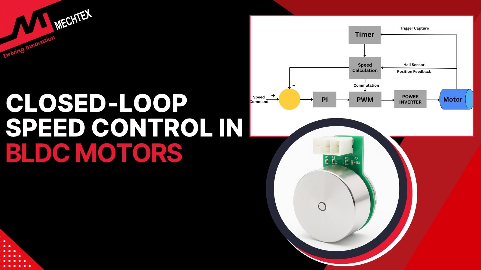
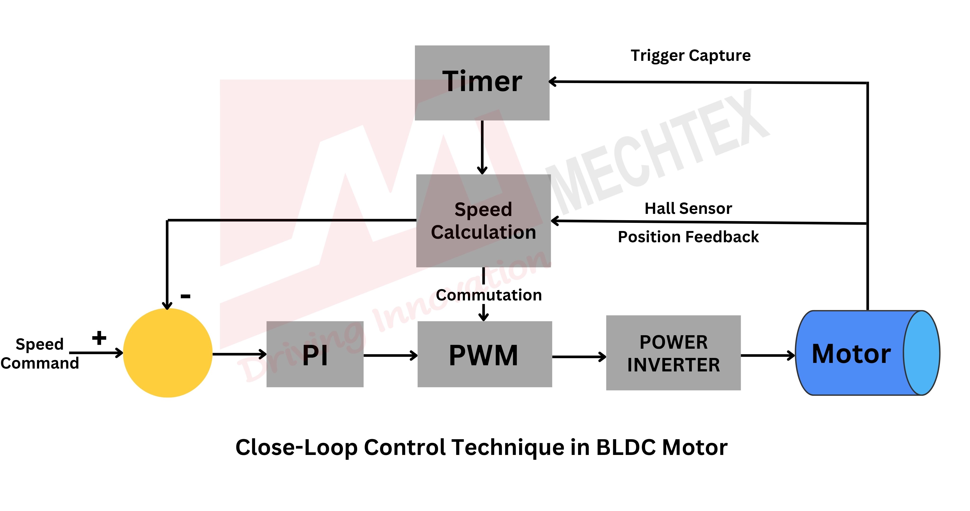
Working Principle of Closed-Loop Speed Control
Close-loop speed control technique operates on a feedback mechanism, such as hall sensor or encoder, to maintain the desired speed of the motor regardless of variation in load and disturbances.
In this technique, a speed sensor continuously monitors the actual speed of the motor and sends this data to the controller.
The controller compares the actual speed of the motor with the reference speed. If there is any deviation, it calculates the error and adjusts the control signals such as voltage, speed, current and PWM duty cycle to minimise the error.

This adjustment is done in real-time using control algorithms like PI (Proportional-Integral), PID (Proportional-Integral-Derivative).
These real-time adjustments ensure that the motor maintains consistent performance under varying load conditions. For BLDC motors, close-loop control enables precise control and stable torque, especially at low speeds under load conditions.
By integrating sensors and control logic, close-loop system offers speed regulation, low energy consumption and enhanced system reliability compared to open-loop system. This makes close-loop system ideal for applications requiring high precision such as robotics, CNC machinery, and electric vehicles.
Also Read
Open-Loop Control vs. Closed-Loop in BLDC Motors
PI Controller
In brushless DC motor (BLDC motor), maintaining constant speed under varying load conditions is essential to provide performance in high precision applications such as robotics, drones, and automation systems.
Close-loop control system addresses the need for constant speed by continuously monitoring the motor speed and adjusting the signals to maintain the desired speed. A commonly used method for this regulation is the Proportional-Integral (PI) controller.
Role of PI Controller
The PI-Controller works by combining the two actions:
- Proportional (P)
It reacts to the current error between the reference speed and actual speed. It provides an output proportional to the magnitude of the error, which helps in reducing the deviation quickly.
- Integral (I)
It accumulates the past errors over time and eliminates the steady-state errors that the proportional term alone cannot address.
Working of PI Controller
Let the error signal be:
e(t) = ω_ref - ω_actual
Where ω_ref is the desired speed and ω_actual is the measured speed.
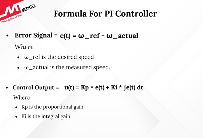
The control output is:
u(t) = Kp * e(t) + Ki * ∫e(t) dt
Where,
- Kp is the proportional gain.
- Ki is the integral gain.
This control output modulates the duty cycle of the PWM signals fed to the BLDC driver, adjusting the motor voltage and thereby the speed.
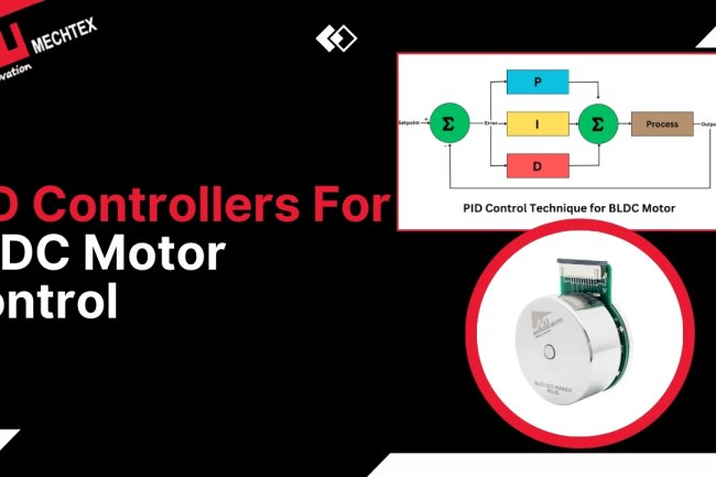
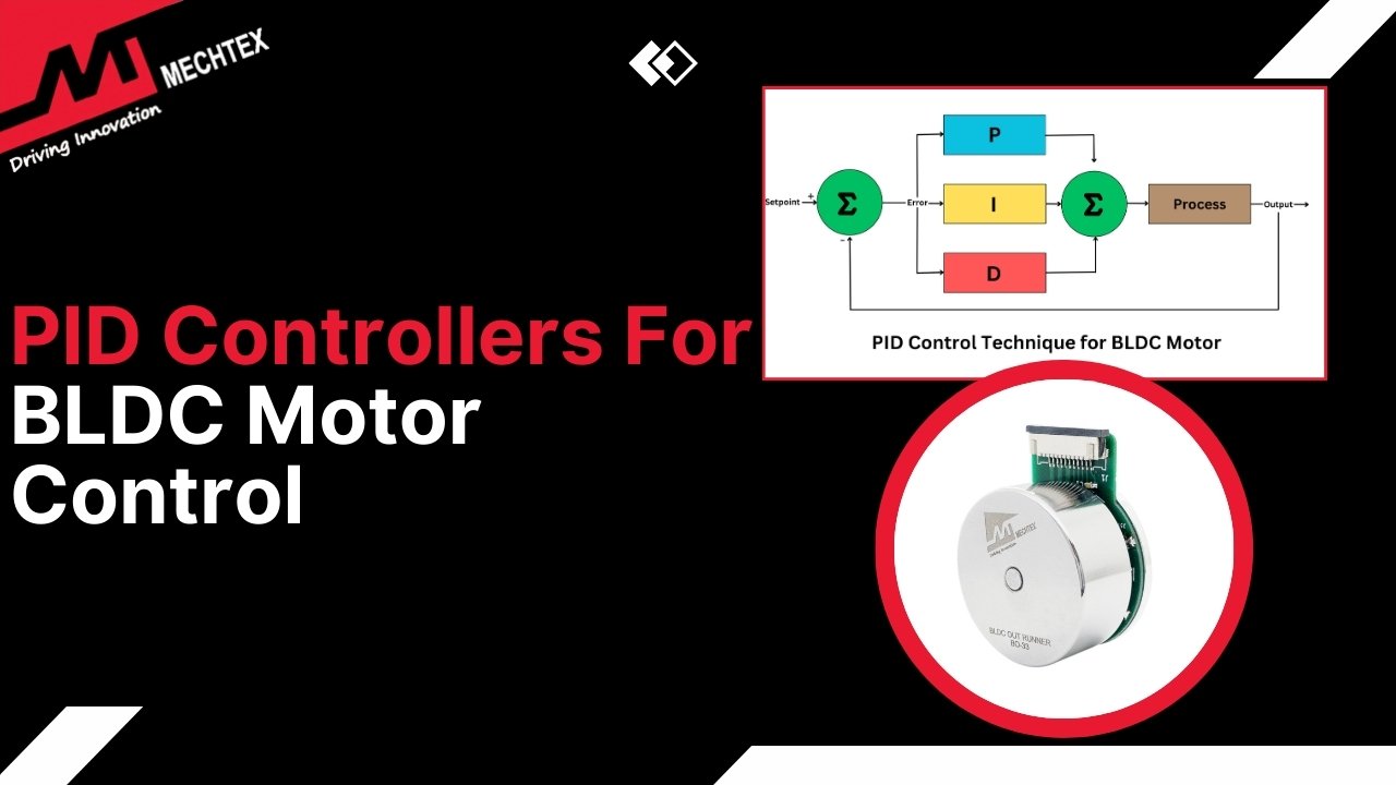
PID Controller
In Brushless DC Motor (BLDC Motor) applications, precise speed regulation is essential for high-performance, especially in dynamic environments wth varying load conditions.
The close-loop speed control ensures that the BLDC motor maintains constant speed despite varying load conditions. One of the most effective methods of close-loop control system to maintain constant speed is Proportional-Integral-Derivative (PID) controller.
Components of PID Controller
- Proportional (P)
Reacts quickly to the current error between the reference speed and actual speed. It provides a control signal proportional to the error.
- Integral (I)
It accumulates past errors over time to eliminate steady-state error that the proportional action alone cannot remove.
- Derivative (D)
It predicts future error based on the rate of change by adding damping and improving system stability.
Working of PID Controller
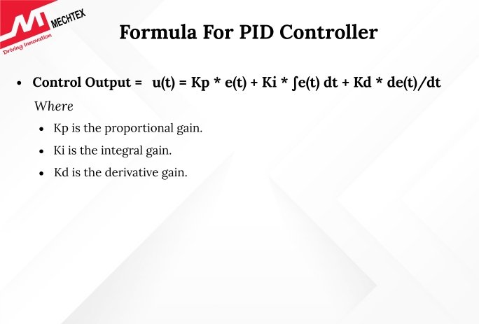
The control law is:
u(t) = Kp * e(t) + Ki * ∫e(t) dt + Kd * de(t)/dt
Where
- Kd is the derivative gain.
This controller provides a more dynamic response and is ideal for applications requiring high precision and fast correction, such as robotics or drones.
State Feedback Control
State feedback control is an advanced close-loop control technique used in BLDC motors for precise speed regulation and torque control.
Unlike conventional control techniques such as PI or PID, which rely on error correction between reference and actual, state feedback control uses a mathematical model and directly regulates the motor by feeding back multiple internal states such as speed, rotor position, and current.
Working of State Feedback Control
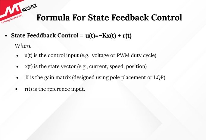
In state feedback control, the control signal is calculated on the full set of internal system variables, which are represented in the state space model. The formula is:
u(t)=−K×(t) + r(t)
Where,
- u(t) is the control input (e.g., voltage or PWM duty cycle),
- x(t) is the state vector (e.g., current, speed, position),
- K is the gain matrix (designed using pole placement or LQR),
- r(t) is the reference input.
This feedback is processed through the controller to calculate the optimal input signal for the inverter or ESC.
Compared to PI/PID control, state feedback offers better dynamic performance, faster response, and improved stability, especially in systems with multiple control objectives like torque and speed regulation.
Conclusion
Choosing the right control strategy for closed-loop speed control in BLDC motors depends on application requirements, system complexity, and desired precision.
While PI controllers offer simplicity and reliability, PID controllers provide a robust balance between speed and accuracy. For cutting-edge applications demanding high dynamic performance, state feedback control is the preferred choice despite its complexity.
As BLDC motors continue to dominate various sectors—from electric vehicles to medical devices—the role of smart, efficient speed control systems becomes ever more critical.
Understanding these control strategies equips engineers and designers with the tools to achieve optimal performance and efficiency across applications.