What is Permanent Magnet Stepper Motor: Basics, Construction, Working, & Applications
A permanent magnet stepper motor is an electromechanical device that converts electrical pulses into small mechanical movements. It uses permanent magnets to create a rotating magnetic field for motion. The PM stepper motor works on the principle of magnetic attraction and repulsion to ensure smooth rotation and high efficiency.
What is a Permanent Magnet Stepper Motor?
A permanent magnet stepper motor is a type of stepper motor that uses permanent magnets to create a rotating magnetic field for motion. This stepper motor is an electromechanical device that converts electrical pulses into small mechanical movements. It results in precise control over the position and speed of the stepper motor without any feedback system, which makes it an open loop control stepper motor.
In comparison to other stepper motors, which require close-loop system feedback devices to achieve precise control, permanent magnet stepper motors offer inherent accuracy in positioning and speed control.
Permanent magnet stepper motors are known for their simplicity, reliability, and accuracy. The presence of the permanent magnet ensures the creation of a strong magnetic field as compared to other stepper motors, resulting in higher torque generation. Unlike other stepper motors, which provide smooth rotation and high efficiency at high speed, permanent magnet stepper motors ensure high torque at low speed, making them ideal for various applications that require fine movements and positioning accuracy.
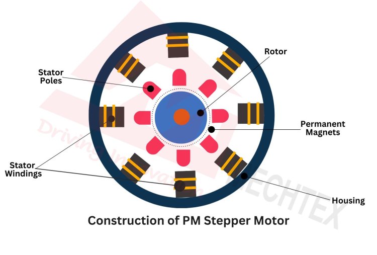
The construction of a permanent magnet stepper motor involves two main components: stator and rotor. The stator is the stationary part of the stepper motor and consists of multiple poles with windings. The rotor is the rotating part of the stepper motor and consists of permanent magnets arranged in cylindrical and disk shapes with alternating north and south poles.
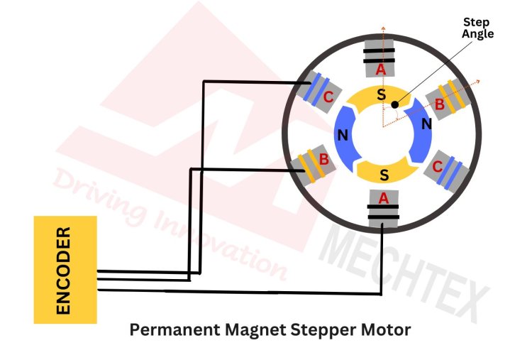
The permanent magnet stepper motor works on the principle of magnetic attraction and repulsion. It involves the interaction between the magnetic fields of the stator and rotor. When electrical pulses are applied to the stator winding in a particular sequence, it generates a rotating magnetic field. The permanent magnet in the rotor aligns itself with the rotating magnetic field of the stator, causing the rotor to rotate at a specific angle (discrete step).
The step angle of the permanent magnet stepper motor can be calculated with the following formula:
Step Angle = 360°/number of steps per revolution
The most common step angles of the permanent magnet stepper motor are 7.5° and 15°.
Permanent magnet stepper motors used in various applications require precision and accuracy such as robotics, 3D printers, CNC machines, and medical devices. These stepper motors are also found in automotive instruments, security cameras, and textile manufacturing equipment.
Construction of Permanent Magnet Stepper Motor
A permanent magnet stepper motor consists of several key components such as stator, rotor, bearing and encoder. These components work together to ensure precise control and accuracy in the movement.
Key components of permanent magnet stepper motors are:
- Stator
Stator is the stationary part of the permanent magnet stepper motor. It consists of multiple windings around its circumference. These windings are made up of insulated copper wire. The configuration of the stator winding includes several poles, which may vary and depend upon the permanent magnet stepper motor’s design. It affects the speed and torque of the stepper motor.
- Rotor
Rotor is the rotating part of the permanent magnet stepper motor. It is made up of various permanent magnets arranged in a cylindrical or disk shape with alternating north and south poles. This arrangement creates a magnetic field that interacts with the stator’s magnetic field and causes the rotor to rotate at a specific angle.
- Bearings
Bearings are placed at the end of the rotor to support its rotation and reduce friction. They ensure smooth rotation of the rotor at a specific angle to achieve accuracy.
- Encoder
The encoder is an electrical feedback device attached to the permanent magnet stepper motor to provide feedback on the rotor’s position. This enhances the movement of the permanent magnet stepper motor and ensures accuracy in operation.
Other Components
- Housing
Housing provides the protection and support to the internal components of the permanent magnet stepper motor. It is made up of durable materials such as aluminium or steel to accommodate bearings.
- Commutator and Brushes
The commutator and Brushes provide electrical contact between the stator and rotor. However, the modern design of stepper motors excludes commutators and brushes and uses advanced methods for electrical contact, such as slip rings.
Working Principle of Permanent Magnet Stepper Motor
The working principle of a permanent magnet stepper motor is based upon magnetic attraction and repulsion of the stator’s windings and rotor’s permanent magnets.
Electrical pulses are sent to the stator windings in a specific sequence by the motor’s encoder. Each pulse energises the particular set of windings and creates magnetic fields. These magnetic fields have their defined north and south poles determined by the direction and magnitude of the current.
The permanent magnets of the rotor align with the magnetic field produced by the stator winding and cause the rotor to rotate in a specific direction.
For example, if the stator's north pole produces a magnetic field, then the rotor’s south pole aligns with it and produces movement.
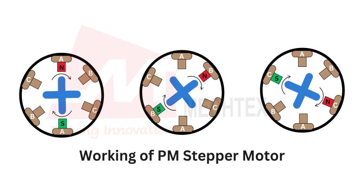
By sequentially energising the stator’s windings, the rotor moves from one position (angle) to the next position (angle) which is called steps. The step angle of the stepper motor depends on the number of poles of stator and rotor.
The speed and direction of the permanent magnet stepper motor are controlled by adjusting the frequency and sequence of current based on the encoder’s feedback. Increasing the frequency increases the rotational speed while changing the order of the pulse reverses the direction of the motor. Continuous energising of the stator winding provides high-holding torque and enables the rotor to hold its position under the load.
Also Read
Applications of Permanent Magnet Stepper Motor
Permanent magnet stepper motors are widely used in various applications due to their precise control, reliability and accuracy in operation.

Some of the major applications of permanent magnet stepper motors are:
- Robotics
Permanent magnet stepper motors are used to control the movement of robotic arms by enabling accurate and repeatable positioning. This characteristic is crucial for robotics arms to perform tasks such as assembly, painting, welding etc.
- Medical Devices
Permanent magnet stepper motors are used in various medical equipment, such as pumps. Their ability to provide precise control over repeatable movements ensures accurate and safe medical treatments.
- Textile Machinery
In textile machinery, permanent magnet stepper motors control the movement of threads and fabrics to ensure precise weaving, knitting and embroidery processes.
Permanent magnet stepper motors are used in the HVAC system to control the damper, valves or fan speed with precision. Their ability to move in fine steps and maintain accuracy in positioning improves the performance of HVAC systems. Their precise control ensures optimal airflow and temperature regulation to enhance the overall energy efficiency and comfort.
Conclusion
The permanent magnet stepper motor is a highly versatile and efficient stepper motor known for its precise control, reliability and accuracy. By using permanent magnets of the rotor to generate the magnetic field, these stepper motors convert electrical pulses into fine movements. This characteristic makes them ideal for applications that require accurate positioning and better speed control. Their robust design and ability to maintain its position under load set it apart from other conventional motors. Overall, permanent magnet stepper motors are essential components in modern automation and control technologies.