Understanding Torque and Speed Curves of Stepper Motors
The torque-speed curve of the stepper motor is the graphical representation of the relationship between the stepper motor's output torque and its speed. This curve shows how much torque the stepper motor can deliver at different speeds which makes this curve a valuable tool for engineers to determine the stepper motor’s suitability for a particular application.
What is a Stepper Motor?
A stepper motor is a type of electric motor that is designed to move in precise and fixed angular steps. This makes them ideal for applications that require accurate positioning. Unlike conventional motors, which rotate continuously, stepper motors move in discrete steps. Each step corresponds to a specific angle which allows for precise control over speed and position.
The construction of stepper motors includes two main components; stator and rotor. The stator is the stationary part of the stepper motor and consists of windings. Each winding is energised in sequence to create a rotating magnetic field. The rotor is a rotating part of the stepper motor made up of permanent magnets. The rotor has teeth, allowing for more precise alignment with the magnetic fields generated by the stator.
Watch the YouTube video by "Sabins Civil Engineering" to know more about the working principle of a stepper motor.
The stepper motor works using multiple coils arranged in phases. When electrical current is supplied to these coils sequentially, the stepper motors move at a specific angle. This angle is known as the step angle. In a typical stepper motor, the step angle ranges from 1.8 degrees to 90 degrees.
Stepper motors are used in various applications such as 3D printers, CNC machines, robotics, and medical devices, where precision is critical. They provide open-loop control, eliminating the need for feedback systems in many applications.
Also Read
Understanding the Hybrid Stepper Motor
What is the Torque and Speed Curve of Stepper Motor?
A torque-speed curve illustrates the relationship between the stepper motor's output torque and its speed. This curve shows how much torque the stepper motor can deliver at different speeds which makes this curve a valuable tool for engineers. By analysing the torque-speed curve, we can determine the stepper motor’s suitability for a particular application.

The torque-speed curve has two key components: Pull-In Torque Curve and Pull-Out Torque Curve.
The Pull-In Torque Curve represents the maximum torque the stepper motor can generate while starting, stopping and reversing without missing a step.
The Pull-Out Torque Curve shows the maximum torque the stepper motor can maintain while running at constant speed. If the load exceeds the torque, the stepper motor may lose steps or stall. This curve is critical for ensuring that the motor maintains accurate positioning during operation.
The torque-speed curve of the stepper motor has three distinct regions: low-speed region, mid-region and high-speed region.
In the Low-speed region, stepper motors produce high torque as inductance allows more current to flow through the winding. In the mid-range region, stepper motors experience a slight drop in torque due to deviation in frequencies. In the high-speed region, the stepper motor’s torque drops significantly as the speed increases due to winding inductance which limits current at high step rates.
Torque and Speed Curve of Stepper Motor
The torque-speed curve of the stepper motor is the graphical representation that shows how the stepper motor’s torque varies with change in speed. In simple terms, it shows how much torque stepper motors can produce at different speeds. This curve is essential for determining the operational limits of stepper motors.
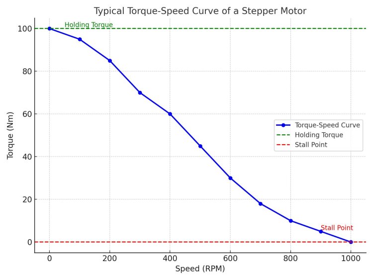
Let’s break down the key concepts of the above torque-speed curve of the stepper motor below:
- Y-axis (Torque)
The vertical axis (Y-axis) represents the torque which is the rotational force produced by the stepper motors. It is usually measured in Newton metres (Nm) or ounce-inches (oz-in).
- X-axis (Speed)
The horizontal axis (X-axis) represents the speed of the stepper motor. It is typically measured in RPM (Revolutions Per Minute) or in terms of steps per second or pulses per second (for stepper motors).
- Downward Slope of Curve
The torque-speed curve of the stepper motor has a downward slope, which means that as the stepper motor’s speed increases, the torque will decrease.
Keypoint of Torque-Speed Curve
- Holding Torque (Zero Speed)
At zero speed, the stepper motor can produce maximum torque which is known as holding torque. It is the maximum torque the stepper motor can resist.
- Pull-In Torque Region
This is the region where the stepper motor can start and stop without losing steps. It indicates the maximum amount of torque the stepper motor can generate at a given speed when starting from rest or reverse direction.
- Pull-Out Torque Region
When stepper motors operate at higher speeds, they enter into the pull-out torque region where torque starts to drop continuously. If the load increases and more torque is required to operate in this region, the stepper motor may lose steps or stall.
- Stall Point
This is the speed beyond which the stepper motor cannot provide any torque. If the load demands more torque than the stepper motor can deliver the motor will get a stall.
Factors Affecting Torque-Speed Curve of Stepper Motor
There are several factors that affect the torque-speed curve of a stepper motor. Some important factors are:
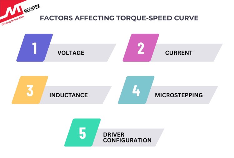
- Voltage
Increasing the voltage supplied to the stepper motor helps to maintain high torque at high speed. High voltage allows the windings of stepper motors to charge and discharge more quickly which enables the stepper motor to respond quickly.
- Current
The current supplied to the windings of the stepper motor directly affects the torque. More current results in more torque, but excessive current leads to overheating and damage.
- Inductance
Stepper motors have inductive windings that oppose the changes in current. At high speeds, inductance winding limits the flow of current into the motor and reduces torque. Lower inductance motors generally have better high-speed performance. Lower inductance stepper motors generally have better high-speed performance.
- Microstepping
Microstepping is a technique used to increase the resolution of the stepper motor by dividing each step into small steps. Microstepping not only improves positional accuracy and smoothness of the stepper motor but also reduces torque at each step.
- Driver Configuration
The type and configuration of the driver in the stepper motor significantly impact its torque-speed curve. Advanced drivers with higher voltage ratings and current regulation features can improve the stepper motor's performance by providing better control over torque and speed.
Conclusion
Understanding the torque-speed curves of stepper motors enables engineers to select the right motor for specific applications. By analysing the curves, they can ensure that the motor provides adequate torque across the required speed range, optimising the system's performance.
A detailed understanding of torque-speed characteristics helps in maximising the efficiency and reliability of stepper motor-driven systems, ensuring smooth operation across different load conditions.